Coaxial gapless guide-through assembly for a filing level sensor

a level sensor and guide-through technology, applied in the direction of liquid bottling, packaging under special atmospheric conditions, liquid dispensing, etc., can solve the problems of inability to adapt sealing elements to filling level sensors, insensitive to filling matter build-up and attachment, and brittleness or flow, etc., to achieve low coefficient of thermal expansion, no discernible softening or melting point, good form and dimensional stability

Inactive Publication Date: 2008-07-22
VEGA GRIESHABER GMBH & CO
View PDF24 Cites 24 Cited by
  • Summary
  • Abstract
  • Description
  • Claims
  • Application Information

AI Technical Summary

Benefits of technology

[0016]One advantage to be attained with the present invention is therefore that due to the precise fit achieved by the machining of the circumferential surfaces of the essentially concentrically arranged components of the guide-through assembly no additional sealing elements need be arranged, so that despite any pressure and / or temperature influences the seal between the interior of the vessel and the interior of the sensor can be permanently ensured. Another advantage of the present invention is that due to the elimination of additional sealing elements, the entire guide-through assembly has a simpler and cheaper construction. Another possible advantage of the present invention is that despite any temperature and / or pressure influences the sealing between the interior of the vessel and the interior of the sensor is permanently ensured, which permanently ensures the operating safety of the entire filling level sensor.
[0017]According to another aspect of the present invention, the guide-through assembly has a process connection arranged within an interior conductor which on the one hand extends through a solid-state insulating body which both surrounds the interior conductor in a positive engagement in a sealing way on its circumferential surface and also fits in the process connection in a positive engagement. As can be seen, the exterior circumferential surface of the interior conductor contacts the insulating body in a closely adjacent relationship, which in turn has its circumferential surface entirely closely fitted in the process connection. By having the insulating sealing body prefabricated as a solid body whose circumferential surface is manufactured to such precision that it sealingly contacts the corresponding circumferential surfaces of either the interior conductor or the process connection, additional sealing elements, for example of elastomeric material, are not needed, which are usually affected by the above-described sealing problems due to the effects of high pressures and / or temperatures.
[0018]While the adjacent circumferential surfaces of the process connection, the interior conductor and the insulating sealing body may be machined to such precision that they contact each other so tightly that in the optimum case no gas exchange is possible through each adjacent pair of circumferential surfaces, the insulating sealing body is made of a plastic material to compensate for any unevenness due to surface defects of the circumferential surfaces, since the plastic material can compensate such unevenness due to a certain resilience. Preferably, the insulating sealing body is of a temperature-insensitive, resilient, pressure-resistant, creep and / or flow-resistant plastic material with dielectric properties, such as a polyimide, which helps to ensure that the guide-through assembly situated between the interior of the vessel and the interior of the sensor remains permanently sealed, also in unfavourable process conditions such as chemical influences, atmospheric process pressures and high temperatures. Trials have shown that the VESPEL® material, especially the SP1 type, is particularly suitable, while other types of VESPEL® or similar generic materials can, of course, also be used in corresponding conditions of application.
[0019]The materials which have been shown to be particularly suitable for the insulating sealing body are distinguished by their good form and dimensional stability, which is due to a well adjusted combination of the essential material parameters. It may, for example, be important that the materials have no discernible softening or melting point. Also, low coefficients of thermal expansion and excellent creep and brittling resistances help to keep dimensions stable. Due to this stability, the insulating sealing body can be made to such low tolerances as have been inconceivable with plastic materials before. This dimensional stability results in the sealing member, for example of VESPEL® or a polyimide, keeping its form and function also in extreme process conditions. The materials which have shown to be particularly suitable, such as VESPEL® or polyimide, combine the favourable dimensional stability with a toughness which conventional plastic materials usually lack. Moreover, these materials have shown to be suitable because they do not melt at temperatures as high as about 290° C. and, for short durations, as high as about 500° C. and therefore remain uniformly dimensionally stable and strong also with high temperatures over longer periods of time.
[0020]As can be seen from the preceding explanations, the interior conductor is circumferentially surrounded by the insulating sealing body which, in turn, is fitted into the process connection. In order to simplify terminology in the following, the exterior circumferential surfaces of the interior conductor, which the insulating sealing body circumferentially contacts in a positive and therefore sealing engagement, will be referred to as the outer circumferential surface of the interior conductor. Similarly, the insulating sealing body has an interior circumferential surface which contacts the exterior circumferential surface of the interior conductor in a positive and therefore sealing engagement and exactly fits onto the latter. Similarly, the insulating sealing body also has an exterior circumferential surface, while the process connection also has an interior circumferential surface which in the assembled state of the insulating sealing body within the process connection fit together in a positive and therefore sealing engagement.
[0021]According to another aspect of the present invention, both the interior circumferential surface of the insulating sealing body and the exterior circumferential surface of the interior conductor have a conical or tapered section, wherein the contours of the two sections are complementary to each other and fit together closely in a positive and therefore sealing engagement, so that the interior conductor can be fitted into the corresponding section of the insulating sealing body in a sealing manner. Similarly, both the interior circumferential surface of the process connection and the exterior circumferential surface of the insulating sealing body have a conical or tapering section, wherein the contours of these two sections are complementary to each other and fit into each other in a positive and therefore sealing engagement, so that the insulating sealing body with its conical or tapering section can be fitted, fully sealed, into the corresponding section of the process connection.

Problems solved by technology

When it is configured as a rod or cable probe, it is particularly insensitive to filling matter build-up and attachment.
However, such materials usually have a drawback in that they begin to get brittle or to flow when exposed to high pressures and / or temperatures, which is why such sealing elements are not suitable for filling level sensors exposed to high pressures and / or temperatures.

Method used


Image

  • Coaxial gapless guide-through assembly for a filing level sensor
  • Coaxial gapless guide-through assembly for a filing level sensor

Examples


Embodiment Construction

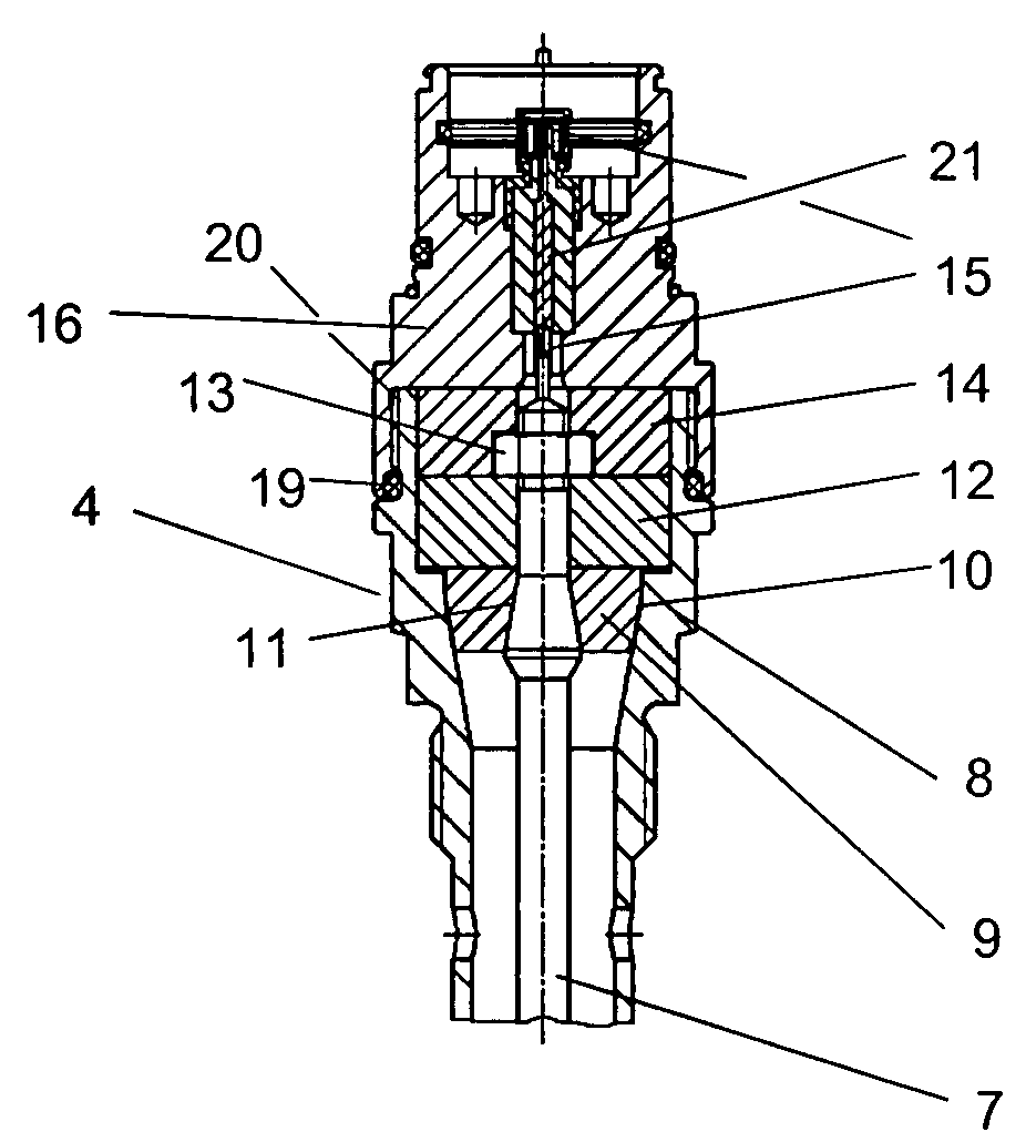
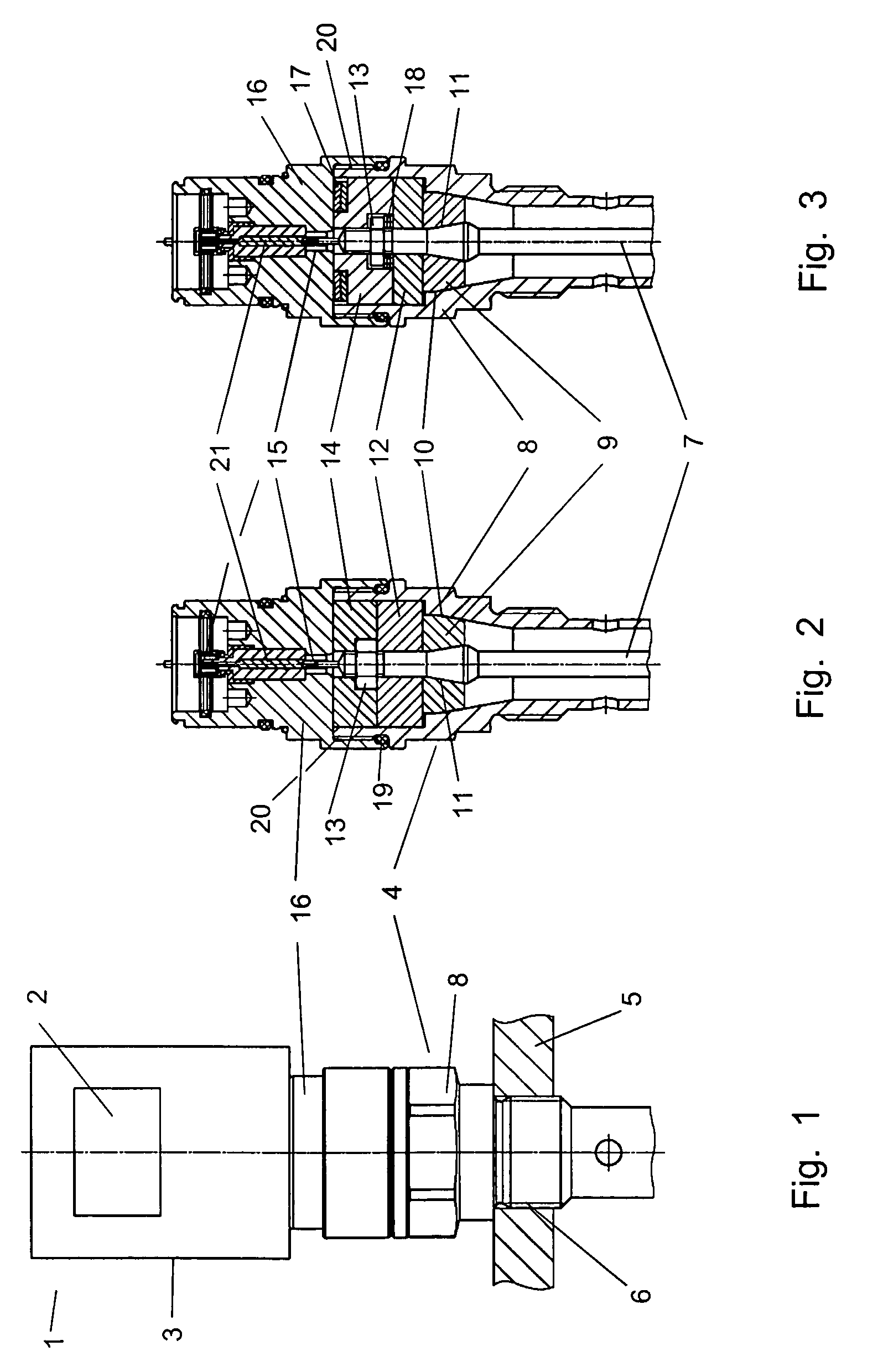
[0035]FIG. 1 shows a filling level sensor 1, such as a TDR filling level sensor or a capacitive filling level sensor, which is fixed in a vessel wall 5. Filling level sensor 1 essentially comprises three housing portions 3, 16, 8 connected to each other. These form the actual sensor housing 3, in which sensor electronics unit 2, only schematically shown, is accommodated. This actual sensor housing 3 is connected to the connection adapter 16, for example, via a screw connection.

[0036]As can be seen from FIG. 2, connection adapter 16 comprises a solid housing portion through which an interior conductor 21 surrounded by a dielectric material is centrally passed. Interior conductor 21 of connection adapter 16 has the function to establish the electrical contact between sensor electronics 2 and interior conductor 7. To do this, interior conductor 21 of connection adapter 16 has corresponding contacting means 15 at both ends, such as sockets or plugs, in or onto which the corresponding co...


PUM


Abstract

The present invention relates to a guide-through assembly (4) for a filling level sensor working according to the principle of delay measurement of guided electromagnetic waves or for a capacitive filling level sensor, which for sealing the interior of the vessel against the interior of the sensor has no elastomeric sealing materials and in particular no elastomeric o-rings seals. This can be ensured by precisely machining the components which are essentially concentrically arranged in the guide-through assembly (4) on their circumferential surfaces (10, 11), so that in an assembled state the components arranged in the guide-through assembly (4), such as the interior conductor (7) and the dielectric materials (9, 12, 14) surrounding the interior conductor (7), contact each other at their mutually adjacent circumferential surfaces (11) in a sealing and positive engagement, so that additional sealing elements are not needed.

Description

CROSS-REFERENCE TO RELATED APPLICATIONS[0001]This application claims the benefit under 35 U.S.C. 119 (e) of U.S. Provisional Application No. 60 / 529,313 filed on Dec. 12, 2003, which is hereby incorporated by reference in its entirety.TECHNICAL FIELD OF THE INVENTION[0002]The present invention relates generally to a guide-through assembly for a filling level sensor of the generic kind more closely defined in the following and to be attached in or on a vessel. In particular, the invention relates to a guide-through assembly for a filling level sensor working according to the principles of the delay measurement of guided electromagnetic waves (a TDR filling level sensor), or for a capacitive filling level sensor, requiring no elastomeric sealing materials and in particular no elastomeric o-ring seals to seal the interior of the vessel against the interior of the sensor.BACKGROUND OF THE INVENTION[0003]For the measurement of filling levels measuring systems are often used which operate ...

Claims


Application Information

Patent Timeline
Patent Type & Authority Patents(United States)
IPC IPC(8): G01D21/00G01F23/00B67D99/00G01F23/26G01F23/284H01R13/52
CPCG01F23/00G01F23/268H01R13/5202G01F23/284H01R2201/20
Inventor DIETMEIER, JUERGEN
Owner VEGA GRIESHABER GMBH & CO
Why Eureka
Try Eureka