Device for connecting a structural element with a holding element spaced apart

a technology of spaced apart connection and structural element, which is applied in the direction of sheet joining, screws, nuts, etc., can solve the problems of unsuitable composite component support devices, components can be damaged, and known devices are unsuitable for many applications, etc., to achieve simple structure, simple method, and simple mounting and/or removal

Active Publication Date: 2018-12-04
FACC
View PDF23 Cites 2 Cited by
  • Summary
  • Abstract
  • Description
  • Claims
  • Application Information

AI Technical Summary

Benefits of technology

[0018]For manufacturing reasons, it is preferred if the distance compensation element comprises a receiving opening for detachably receiving an abutment element, by means of which unscrewing the distance compensation element from of the insertion part can be blocked in the mounted state. Due to the detachable arrangement of the abutment element in the receiving opening the device can be mounted and / or removed in a particularly simple manner.
[0019]In this embodiment, it is favorable if a particularly U-shaped clip element is provided as an abutment element, which clip element in the mounted state projects into the longitudinal bore of the distance compensation element. The clip element can be inserted with its ends in the corresponding receiving openings of the distance compensation element. In the mounted state, the clip element blocks any adjustment of the distance compensation element beyond reaching the second state of the device, the second state having the maximum length. With respect to a particularly cheap and simple construction the clip element provided may be a wire, in particular with a circular cross-section, the recesses of the distance compensation element being designed accordingly. The clip element is preferably elastically deformable, so that in the mounted state the clip element can be secured against unintentional removal by means of elastic deformation of the ends of the clip element which are plugged through the receiving openings.
[0020]For a non-rotatable connection between the connection screw and the distance compensation element upon screwing in the connection screw, it is favorable if a spring element which is elastically deformable by means of the connection screw is provided as an entraining element. In engagement with the connection screw the spring element is deformed elastically, the restoring forces of the spring element effecting a friction fit between the connection screw and the spring element. Upon reaching the abutment position on the holding element, frictional forces will occur between the abutment surface of the distance compensation element and the holding element, so that the friction fit between the connection screw and the spring element is overcome when the connection screw is further twisted. In this state, the connection screw can be fixed in the corresponding thread of the holding element.
[0021]To be able to reliably ensure entrainment of the distance compensation element upon screwing in the connection screw, it is of advantage if the spring element is arranged in a holding section of the distance compensation element in a torque-proof and axially immovable manner. For this purpose, it is favorable if the spring element and the longitudinal bore of the distance compensation element have different cross-sectional shapes. Furthermore, the holding section may have a cross-sectional shape that is different from an adjacent portion of the longitudinal bore.
[0022]To obtain the friction fit between the connection screw and the distance compensation element it is favorable if the spring element comprises two expansion legs that can be spread by means of the connection screw and are arranged essentially in parallel to one another, which expansion legs are connected to one another via a connecting section. The expansion legs can be pressed outwards in engagement with the connection screw in an essentially perpendicular manner to the principal plane of the expansion legs, the restoring forces of the expansion legs causing a friction fit between the connection screw and the spring element. The connecting section preferably comprises two connecting legs arranged at an obtuse angle to one another, which may facilitate deformation of the expansion portions.

Problems solved by technology

As a disadvantage, the component can be damaged by the tightening moment of the screw.
This is of particular disadvantage if the component is made from a fiber composite material.
In addition, given the lack of space, the known device would be unsuitable for supporting composite components.
Therefore, the known embodiments are not suited for many applications, in particular in the aircraft construction.
For reasons of stability and load capacity, it is disadvantageous for the support of structural components made from composite materials if the connection screw is fixed with the screw head on the upper side of the composite material.
Such an embodiment, however, would be unsuitable or unfavorable for the support of composite components due to lack of space.

Method used


Image

  • Device for connecting a structural element with a holding element spaced apart
  • Device for connecting a structural element with a holding element spaced apart
  • Device for connecting a structural element with a holding element spaced apart

Examples


Embodiment Construction

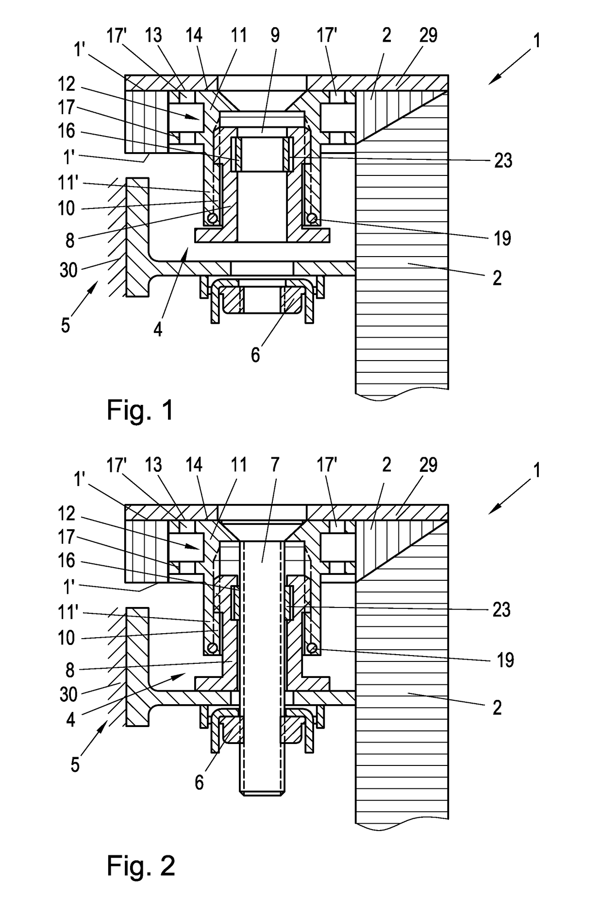
[0037]FIG. 1 shows a structural element 1 which is used as a storage compartment in the aircraft construction. In particular, the structural element 1 is made from a fiber-reinforced plastic composite material. In the shown design, the structural element 1 comprises to plate elements 2 arranged at right angles. In FIG. 1, on the upper side of the one plate element 2 a surface material 29, for example a veneer is indicated. Furthermore, a device 4 for connection of the structural element 1 with a holding element 5 is provided, which is arranged on a structural body 30 (schematically shown in the drawing). In the shown embodiment, the holding element 5 is designed as a holding clip or bracket, in which a clip nut 6 having a thread for screwing in a connection screw 7 is received.

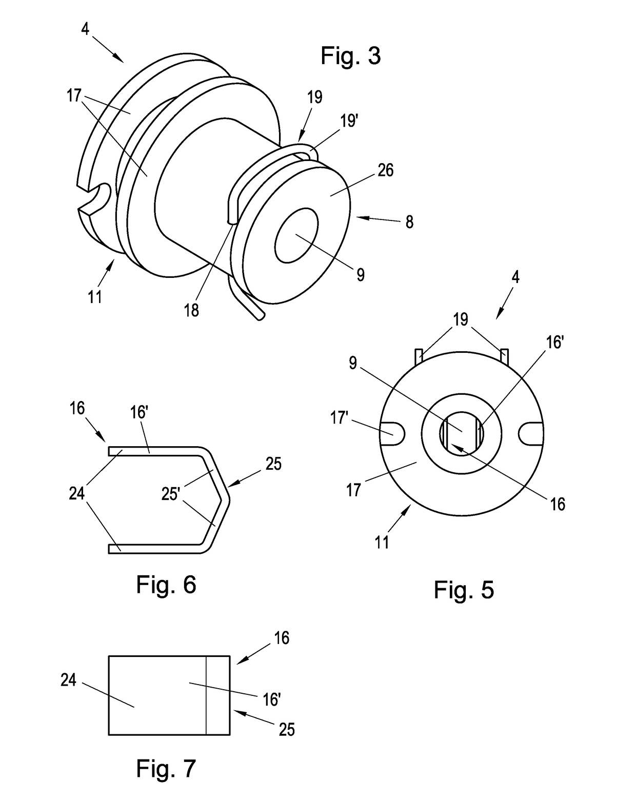
[0038]Furthermore, it can be seen from FIG. 1 that the device 4 comprises a distance compensation element 8 having a central longitudinal bore 9 for the passage of the connection screw 7. The distance compensa...


PUM


Abstract

A device for a spaced apart connection of a structural element, in particular made from a fiber-reinforced plastic composite material, with a holding element by means of a connection screw, with a distance compensation element comprising a longitudinal bore for the passage of the connection screw, and with an entraining element arranged in the longitudinal bore, which entraining element can be connected to the connection screw by means of a friction fit, so that the distance compensation element can be transferred into an abutment position bridging the distance between the structural element and the holding element by screwing in of the connection screw, wherein the distance compensation element is connected to an insertion part via a screw connection, which insertion part comprises a fastening section that can be arranged within the structural element for bonding with the structural element.

Description

CROSS REFERENCE TO RELATED APPLICATIONS[0001]The present application is a U.S. National Phase of International Patent Application Serial No. PCT / AT2015 / 050060, entitled “DEVICE FOR CONNECTING A STRUCTURAL ELEMENT WITH A HOLDING ELEMENT SPACED APART,” filed on Mar. 6, 2015, which claims priority to Austrian Patent Application No. A 50167 / 2014, filed on Mar. 7, 2014, the entire contents of each of which are hereby incorporated by reference for all purposes.TECHNICAL FIELD[0002]The invention relates to a device for spaced apart connection of a structural element, in particular made from a fiber-reinforced plastic composite material, with a holding element by means of a connection screw, with a distance compensation element comprising a longitudinal bore for the passage of the connection screw, and with an entraining element arranged in the longitudinal bore, which entraining element can be connected to the connection screw by means of a friction fit, so that the distance compensation e...

Claims


Application Information

Patent Timeline
Patent Type & Authority Patents(United States)
IPC IPC(8): F16B43/02B64D11/02B64C1/12F16B5/02F16B5/01
CPCF16B5/01F16B5/0233B64D11/02B64C1/12F16B5/025F16B5/0283F16B37/042F16B39/32
Inventor HASELBERGER, CHRISTOPHKAMMERER, BERNHARD
Owner FACC
Why Eureka
Try Eureka