Ozone generator with position-dependent discharge distribution

a technology of ozone generator and position-dependent discharge, which is applied in the direction of corona discharge, energy input, water/sewage treatment by oxidation, etc. it can solve the problems of unavoidable temperature gradient along the way, impair the efficiency of ozone generator, waste heat, etc., and achieve free fabric cross-sectional area

Active Publication Date: 2018-07-05
XYLEM IP MANAGEMENT SARL
View PDF2 Cites 0 Cited by
  • Summary
  • Abstract
  • Description
  • Claims
  • Application Information

AI Technical Summary

Benefits of technology

[0021]Here it is advantageous if the free cross-sectional area of the fabric increases continually or in sections in ...

Problems solved by technology

Most of the electrical power that has to be supplied to an ozone generator results in waste heat.
A mechanism that impairs the efficiency of an ozoniser is the unavoidable temperature gradient that arises along the tubes between the cooling water en...

Method used


Image

  • Ozone generator with position-dependent discharge distribution
  • Ozone generator with position-dependent discharge distribution

Examples


Embodiment Construction

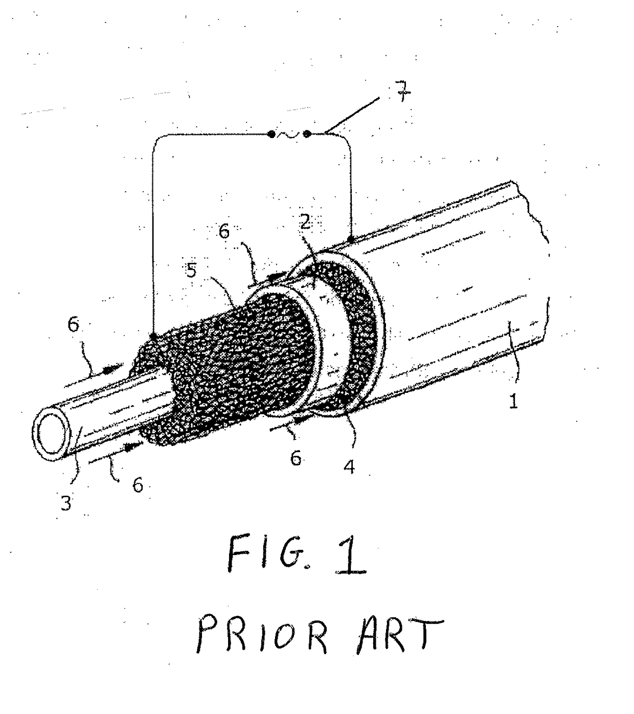
[0028]FIG. 1 shows an electrode arrangement of an ozone generator, as is known from DE 10 2011 008 947 A1. Such ozone generators are used grouped together in a single ozoniser. Here the ozone generators are arranged in parallel to one another between two tube sheets in the manner of a tube-bundle heat exchanger and electrically connected in parallel. The ozone generator shown has a tubular outer electrode 1, a similarly tubular dielectric 2 and an internal rod 3, wherein the individual components are shown truncated and pulled apart in the axial direction. The arrangement is rotationally symmetric. The outer electrode 1, the dielectric 2 and the rod 3 are aligned concentrically to one another. Between the outer electrode 1 and the dielectric 2 is a wire mesh 4, which fills the interstice. Between the dielectric 2 and the rod 3 a corresponding fabric in the form of a wire mesh 5 is provided, which similarly fills the interstice located there. The outer electrode 1 is formed as a stai...


PUM


Abstract

An ozone generator includes a high-voltage electrode and at least one counter electrode, which define an interstice in which at least one dielectric is arranged and through which a gas flows in the flow direction, the high-voltage electrode and the at least one counter electrode being provided with a connection for an electrical voltage supply to generate silent discharges, and a wire fabric being arranged in the gas flow and its density decreasing in the flow direction.

Description

CROSS-REFERENCE TO RELATED APPLICATIONS[0001]This patent application is a U.S. National Phase Patent Application of PCT Application No. PCT / EP2016 / 050790, filed Jan. 15, 2016, which claims priority to German Patent Application No. 102015002103.6, filed Feb. 23, 2015, each of which is incorporated by reference herein in its entirety.FIELD OF THE INVENTION[0002]The present invention relates to an ozone generator, a wire fabric for use in a gas flow of an ozone generator, and an electrode arrangement.BACKGROUND OF THE INVENTION[0003]Generic ozonisers comprise a plurality of ozone generators, arranged in parallel to one another between two tube sheets in the manner of a tube-bundle heat exchanger. Internally, the tubes create discharge chambers in the form of hollow cathodes. Anode rods with dielectric are arranged in these discharge chambers, which during operation are impinged upon by a high voltage and which cause a silent discharge between the anode rod and the tube. An oxygenated g...

Claims


Application Information

Patent Timeline
IPC IPC(8): C01B13/11H01T19/00H01T23/00
CPCC01B13/11H01T19/00H01T23/00C01B2201/14C01B2201/12C01B2201/22Y02P20/129B01J19/088C02F1/78
Inventor FIEKENS, RALFFIETZEK, REINERSALVERMOSER, MANFREDBRUGGEMANN, NICOLE
Owner XYLEM IP MANAGEMENT SARL
Why Eureka
Try Eureka