Impact tool

a tool and impact technology, applied in the field of impact tools, can solve the problems of short working life of magnetic torque sensors, significant errors in measuring signals, and short working life of measuring signals, and achieve the effects of low clock frequency, high working life and extremely cheap units of measuremen

Active Publication Date: 2020-07-16
DINO PAOLI
View PDF0 Cites 1 Cited by
  • Summary
  • Abstract
  • Description
  • Claims
  • Application Information

AI Technical Summary

Benefits of technology

[0017]Further, this unit of measurement enables a measuring signal to be obtained that is substantially free of measuring errors because an acquisition system for acquiring the measuring signal, associated with the impact tool according to the invention to acquire the measuring signal in order to permit reading thereof, is not substantially altered by the operating conditions of the impact tool that require great and complex dynamic stress. Also, the unit of measurement is tough and has a long working life because of the f...

Problems solved by technology

One drawback of known pneumatic impact tools of the prior art is that the measuring signal is affected by significant errors.
The presence of errors in the measuring signal is particularly significant inasmuch as the measuring signal detected in the pneumatic impact tool...

Method used


Image

  • Impact tool
  • Impact tool
  • Impact tool

Examples


Embodiment Construction

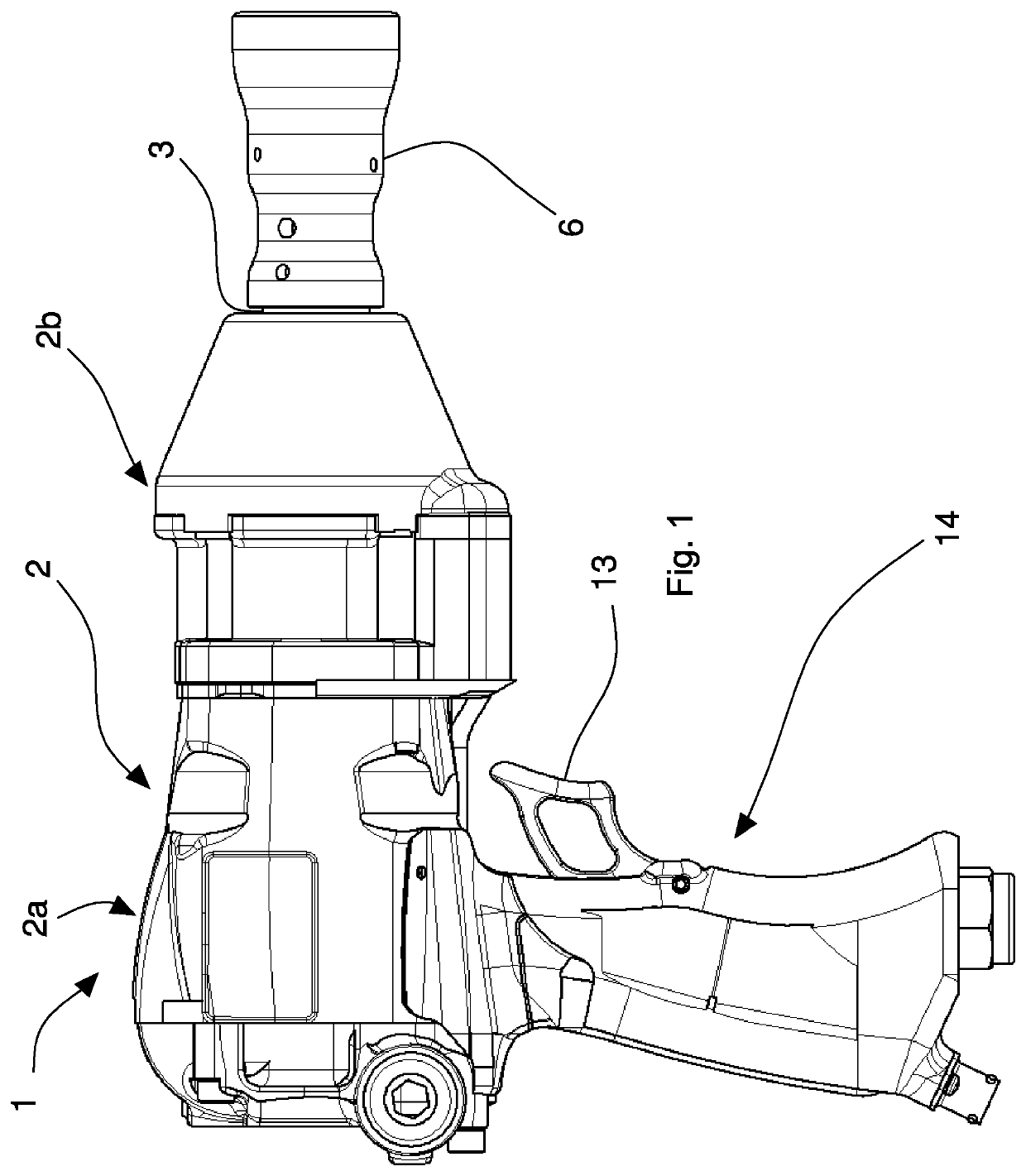
[0039]With reference to the aforesaid Figures, overall with 1 an impact tool has been indicated that, in the specific case, is an impact wrench usable, for example, for fitting and removing wheels of vehicles, in particular racing cars or motorcycles.

[0040]With reference in particular to FIG. 1, the impact tool 1 comprises a containing and protection casing 2 provided with a first part 2a arranged for housing internally a rotating hammer (not shown in the Figures) rotated by a motor (also not shown in the Figures). In the specific case, the motor is of pneumatic type. The rotating hammer acts as a flywheel for accumulating mechanical energy.

[0041]In the first part 2a a grip 14 is obtained for gripping of the impact tool 1 by an operator to facilitate the operations of fitting or removing one or more wheel of vehicles.

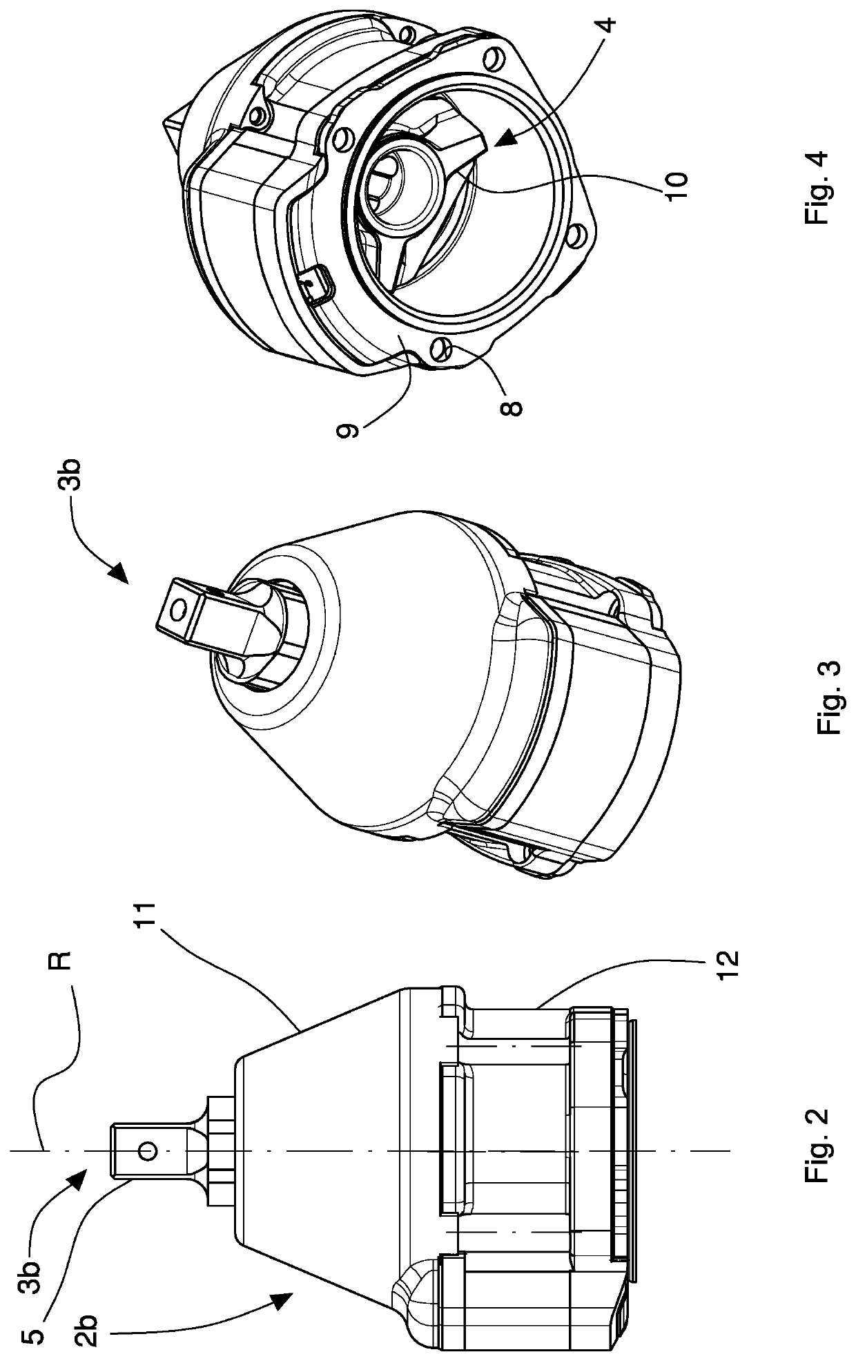
[0042]The impact tool 1 comprises, further, an output shaft 3 rotatable around a rotation axis R (FIG. 2). The output shaft 3 can have, as in the specific case, a proxi...


PUM


Abstract

An impact tool comprises:
    • a casing;
    • a rotating hammer arranged in the casing and rotatable by a motor;
    • a rotating interface element arranged in the casing and rotatable by the hammer by a series of impacts;
    • an output shaft rotating around a rotation axis, the output shaft having a proximal end fixed to the interface element and a distal end protruding from the casing, the distal end ending with a connecting element for removable connection to an outer mechanical adaptor;
    • a unit of measurement arranged for obtaining torque of the output shaft by a torque sensor mounted to the output shaft, the unit of measurement comprising a fixed measuring assembly mounted integrally to the casing and a rotating measuring assembly mounted so as to rotate integrally with the rotating output shaft;
    • the fixed measuring assembly being configured to generate a supply signal and transmit the supply signal to the rotating measuring assembly to supply electrically the rotating measuring assembly;
    • the rotating measuring assembly being configured to detect a measuring signal indicating the torque and condition the measuring signal in order to be able to send the measuring signal to the fixed measuring assembly;
    • in which the fixed measuring assembly and the rotating measuring assembly comprise electronic devices that execute a two-directional communication in contactless mode by magnetic coupling between the fixed measuring assembly and the rotating measuring assembly, the communication being configured to supply magnetically the torque sensor and permit transmission of the measuring signal conditioned by the rotating measuring assembly to the fixed measuring assembly.

Description

BACKGROUND OF THE INVENTION[0001]The invention relates to an impact tool, in particular an impact wrench.[0002]The present invention can be used for locking and unlocking a bolt on a threaded hub of a wheel or a nut on a threaded pin provided in a wheel, for example for rapidly changing the wheels of a vehicle during a race.[0003]The invention relates to an impact tool in which: a rotating mass, for example a hammer, which acts as a flywheel for storing mechanical energy, is rotated by a motor, in particular of pneumatic type; a rotating shaft is fixed to an anvil rotated by the hammer by a series of impacts, for example one impact for each rotation revolution; the connecting mechanism between the hammer and the anvil comprises a clutch that, after each impact, leaves the hammer free again to rotate and which can be driven, for example, by a cam system. In use, a bush is connected removably to the rotating shaft.[0004]The invention relates to an impact tool having a torque sensor op...

Claims


Application Information

Patent Timeline
IPC IPC(8): B60B29/00B25B23/145B25D9/06
CPCB25D2250/051B25D9/06B25D2250/045B25D2250/205B60B29/006B25D2250/221B25D2250/141B25B23/1453B25D2250/181B25B23/1475
Inventor PAOLI, PATRIZIAGALLONI, FEDERICOBORSETTO, EMANUELE
Owner DINO PAOLI
Why Eureka
Try Eureka