Electrical connector for reliably mounted on a printed circuit board

a technology of printed circuit board and connector, which is applied in the direction of coupling device connection, coupling protective earth/shielding arrangement, two-part coupling device, etc., can solve the problems of board mounting legs being likely to loosen or even separate from the pcb, and the mounting arrangement does not provide strong external resistan

Inactive Publication Date: 2008-07-22
HON HAI PRECISION IND CO LTD
View PDF8 Cites 12 Cited by
  • Summary
  • Abstract
  • Description
  • Claims
  • Application Information

AI Technical Summary

Benefits of technology

[0006]Accordingly, an object of the present invention is to provide an electrical connector to be firmly mounted on a printed circuit board (PCB) for ensuring proper resistance of the board mounting legs against the force applied thereto.

Problems solved by technology

Such a mounting arrangement does not provide strong resistance to external forces that occur when a mating connector is inserted into or removed from the electrical connector.
After repeated insertion and removal of the mating connector into / from the hollow opening, the board mounting legs will be likely to loose or even separate from the PCB.

Method used


Image

  • Electrical connector for reliably mounted on a printed circuit board
  • Electrical connector for reliably mounted on a printed circuit board
  • Electrical connector for reliably mounted on a printed circuit board

Examples


Embodiment Construction

[0015]Reference will now be made in detail to the preferred embodiment of the present invention.

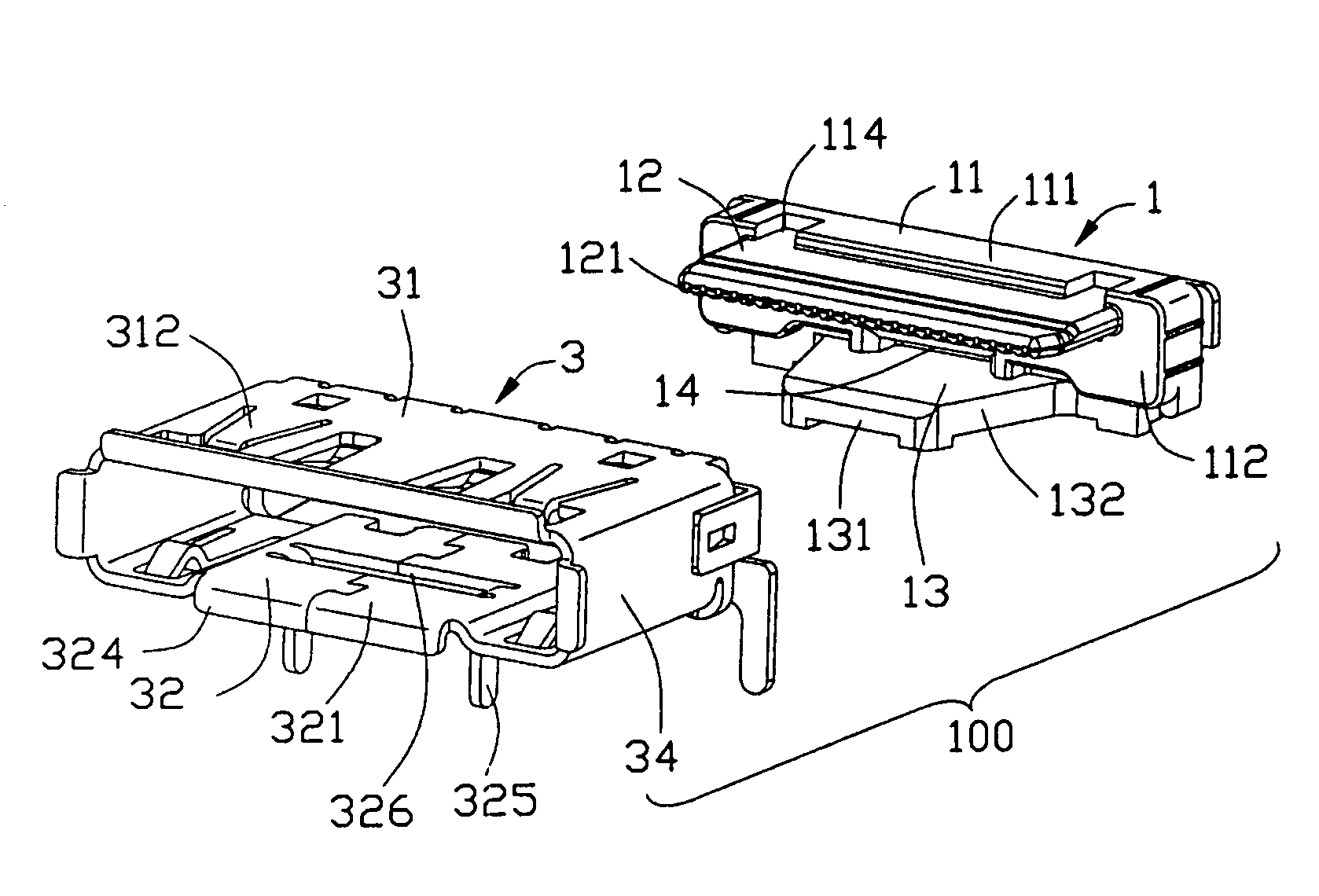
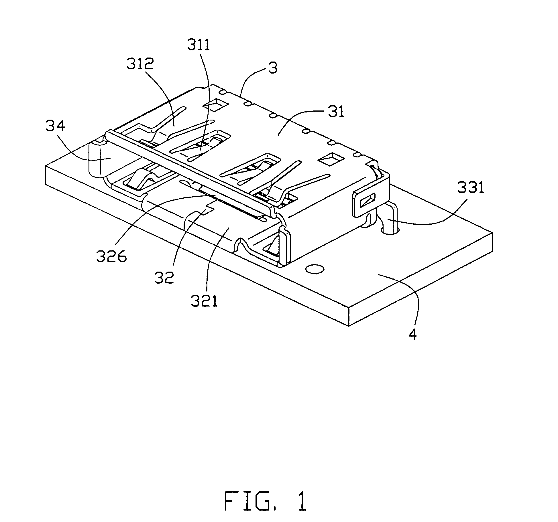
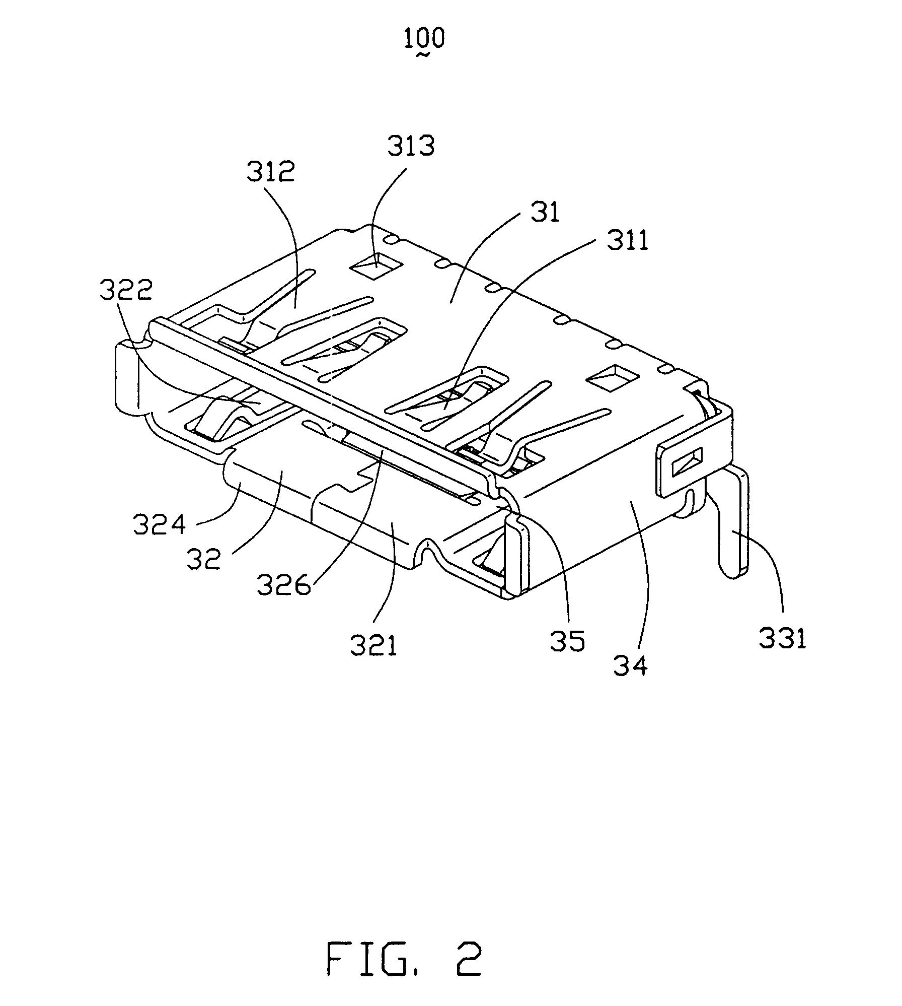
[0016]Referring to FIGS. 1 to 5, an electrical connector 100 mounted on a printed circuit board 4 (PCB) comprises an insulative housing 1, a plurality of contacts 2 retained in the insulative housing 1 and a metal shield 3 enclosing the housing 1.

[0017]The insulative housing 1 includes a base 11, a tongue plate 12 and a bottom plate 13. The base 11 includes a top wall 111, a front wall 112 and a rear wall 113 disposed opposite to the front wall 112. The top wall 111 defines a pair of recesses 114 in communication of the tongue plate 12. The tongue plate 12 and the bottom plate 13 respectively extend forwardly from upper and lower portions of the front wall 112 wherein the upper surface of the tongue plate 12 is a little lower than the top wall 111. The tongue plate 12 extending along the longitude direction of the housing 1. A plurality of horizontal passageways 121 are disposed in a lowe...


PUM


Abstract

An electrical connector (100) includes an insulative housing (1) defining a number of passageways (121) for receiving corresponding contacts (2), and a metal shield (3) enclosing the insulative housing (1). The metal shield has a top face (31), a bottom face (32) and a pair of side faces (33). The bottom face includes a pair of first board mounting legs (325) downwardly and a slot (326) between the first board mounting legs (325). The first board mounting legs (325) are disposed in communication of the slot (326) and mounted on a printed circuit board (4). The length of the slot (326) is equal to the total length of the first board mounting legs (325). With the addition of the first board mounting legs (325), the connector (100) can be more stably mounted on the printed circuit board.

Description

BACKGROUND OF THE INVENTION[0001]1. Field of the Invention[0002]This invention generally relates to an electrical connector, and more particularly to an electrical connector which can be stably mounted on a printed circuit board (PCB).[0003]2. Description of the Prior Art[0004]U.S. Pat. No. 5,779,489, discloses a conventional electrical connector which includes an insulative housing, a plurality of contacts retained in the insulative housing and a metal shield enclosing the insulative housing. The metal shield defines a pair of side walls and a couple of board mounting legs respectively extending downwardly from the side walls. The electrical connector is mounted on a PCB solely by way of its two board mounting legs that are positioned at the end of the electrical connector. Such a mounting arrangement does not provide strong resistance to external forces that occur when a mating connector is inserted into or removed from the electrical connector. Because this electrical connector i...

Claims


Application Information

Patent Timeline
Patent Type & Authority Patents(United States)
IPC IPC(8): H01R13/648H01R12/71H01R12/58
CPCH01R23/6873H01R13/506H01R12/7011H01R12/716H01R12/724H01R13/658
Inventor XIAO, XUE-YUANZHANG, GUO-HUAHU, JIN-KUI
Owner HON HAI PRECISION IND CO LTD
Why Eureka
Try Eureka