Particle beam nozzle transport system

a technology of particle beam and nozzle, which is applied in the field of particle sources, can solve the problems of limiting the flexibility of treatment, changing the nozzle, and requiring a separate set of expensive particle beam transport optics for each separate path

Inactive Publication Date: 2008-07-22
VARIAN MEDICAL SYSTEMS
View PDF2 Cites 150 Cited by
  • Summary
  • Abstract
  • Description
  • Claims
  • Application Information

AI Technical Summary

Problems solved by technology

One limitation of this arrangement is that each separate path requires a separate set of expensive particle transport optics and a separate particle beam nozzle.
Changing nozzles is a time consuming and labor intensive process that limits the flexibility of treatments particularly between successive patients and causes system downtime.

Method used


Image

  • Particle beam nozzle transport system
  • Particle beam nozzle transport system
  • Particle beam nozzle transport system

Examples


Embodiment Construction

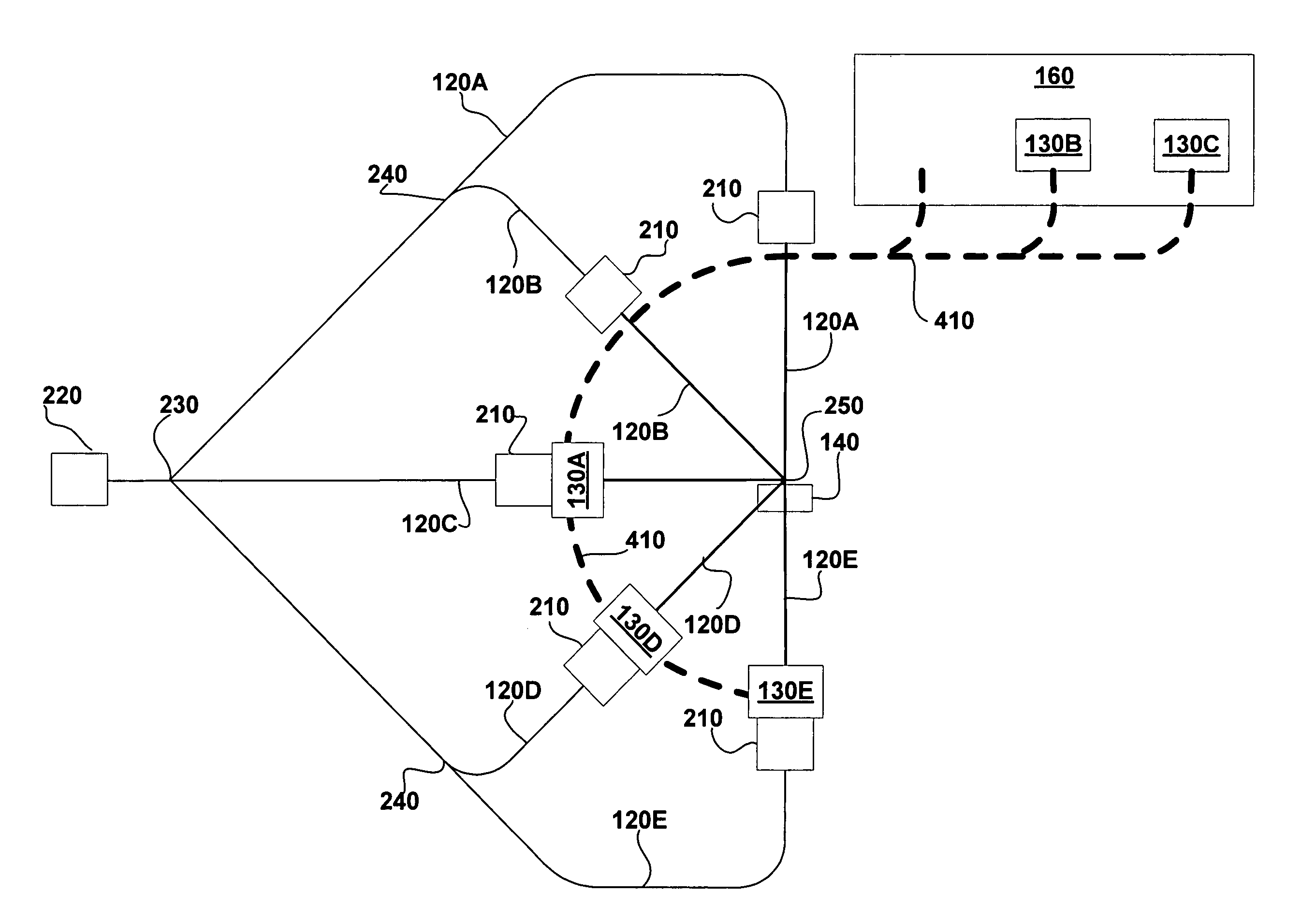
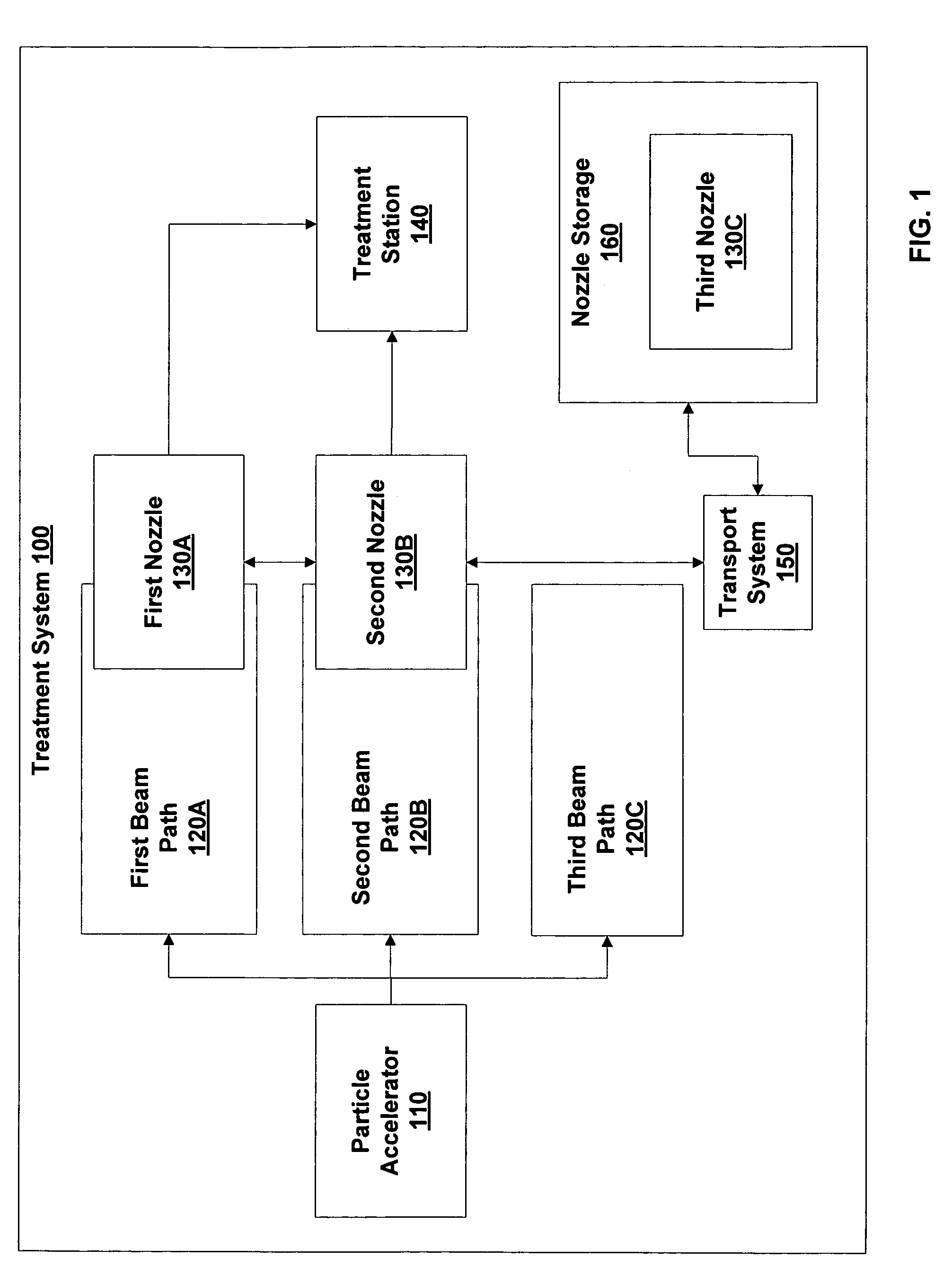
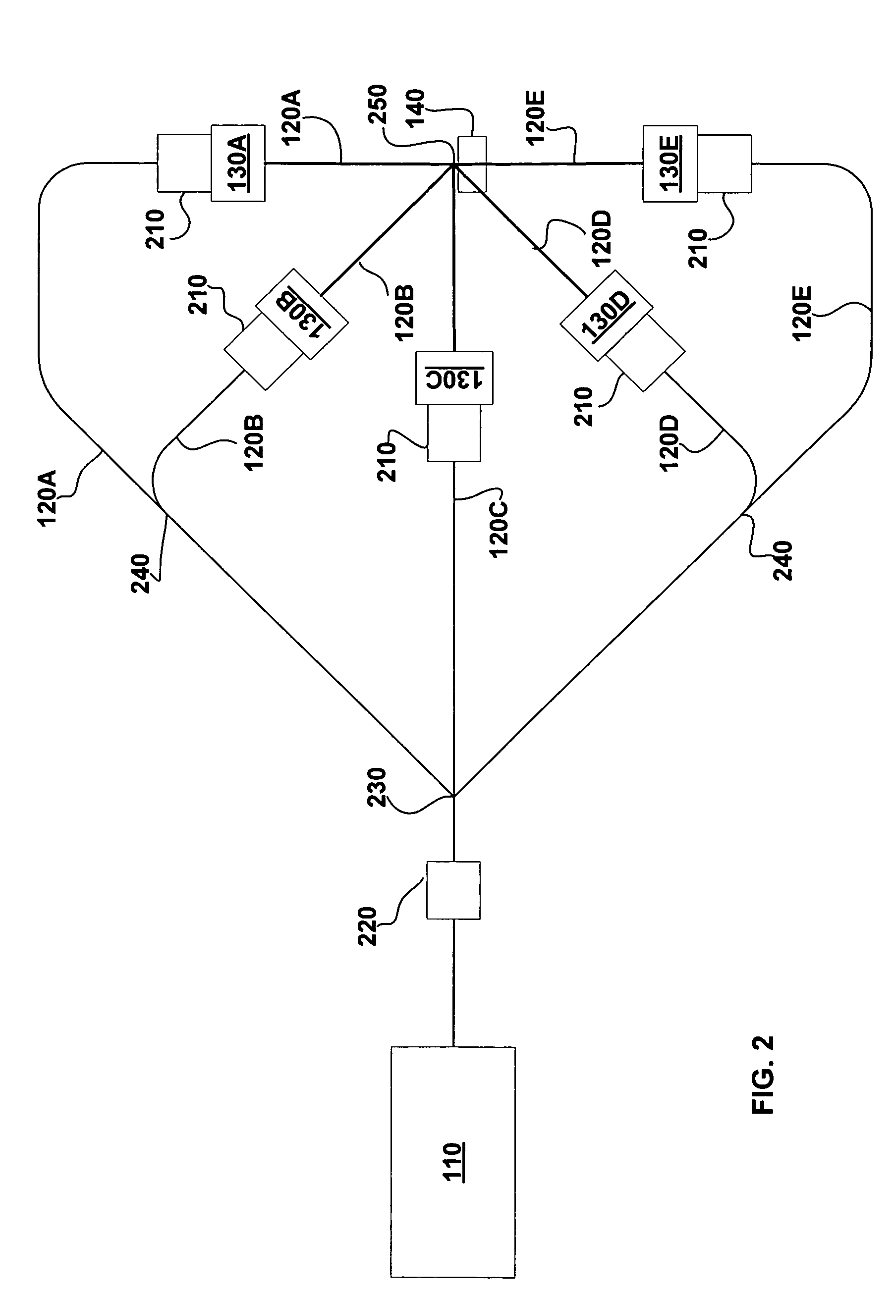
[0034]Some embodiments include three or more alternative particle beam paths through which a particle beam can be delivered to a particular treatment station. At least part of each particle beam path typically includes a separate set of particle transport optics such as magnets or electric fields. The three or more particle beam paths may lie in a single plane or in two or more different planes. The three or more particle beam paths may also be configured to arrive at the treatment station at a variety of different angular separations.

[0035]In some embodiments, the complexity of having multiple particle beam paths is reduced by the inclusion of particle beam nozzles that can be moved from one particle beam path to another automatically, e.g., under control of a processing unit or under the control of a device configured to operate without human intervention. For example, a particular particle beam nozzle may be moved from a first particle beam path to a second particle beam path. Th...


PUM


Abstract

An improved particle beam treatment system optionally includes exchangeable particle beam nozzles. These particle beam nozzles may be automatically moved from a storage location to a particle beam path or between particle beam paths for use in medical applications. Movement may be achieved using a conveyance, gantry, rail system, or the like. The improved particle beam treatment system optionally also includes more than two alternative particle beam paths. These alternative particle beam paths may be directed to a patient from a variety of different angles and in different planes.

Description

BACKGROUND[0001]1. Field of the Invention[0002]The invention is in the field of particle sources and more specifically in the field of particle sources configured for medical applications.[0003]2. Related Art[0004]It has been shown that high-energy particles can be advantageously used for medical treatment of cancer. These high-energy particles typically have energies greater than 20 MeV (million electron volts). For example, protons with energies between 70 MeV and 250 MeV can be used to deposit energy at a very precise depth within a human body.[0005]High-energy protons are generated in a particle accelerator and delivered to a patient at a treatment station. A typical treatment station includes an adjustable gurney or chair configured to position the patient relative to a fixed proton beam. In some instances, the output of the particle accelerator is directed through two alternative paths using particle transport optics such as magnets and electric fields. For example, in one ins...

Claims


Application Information

Patent Timeline
Patent Type & Authority Patents(United States)
IPC IPC(8): G21G1/00
CPCA61N5/10A61N5/1079A61N5/1081H05H7/00A61N5/1084A61N2005/1087H01J2235/186H01J35/186
Inventor GUERTIN, TIMOTHYMARC, MARCEL R.
Owner VARIAN MEDICAL SYSTEMS
Why Eureka
Try Eureka