Hinge structure for flat visual display device

a visual display device and hinge technology, applied in the direction of wing accessories, instruments, machine supports, etc., can solve the problems of user inconvenient adjustment of external force in both sides of the rotation shaft, user may not easily move the pivotal member, etc., and achieve the effect of convenient adjustment and safer placemen

Inactive Publication Date: 2008-07-29
LG ELECTRONICS INC
View PDF26 Cites 15 Cited by
  • Summary
  • Abstract
  • Description
  • Claims
  • Application Information

AI Technical Summary

Benefits of technology

[0012]According to an aspect of the invention to obtain the above objects, it is provided a hinge structure for a flat visual display device comprising: a fixed plate; pivotal plates; a rotation shaft inserted into vertical planes of the fixed and pivotal plates for allowing relative rotational movement; rotation shaft-fixing ends in both ends of the rotation shaft for allowing the pivotal plates fitted around the ends of the rotation shaft to rotate together with the rotation shaft; a braking unit securely settled in the fixed plate and having a braking member for surrounding the outer circumference of the rotation shaft to generate braking force in the rotation shaft; stoppers folded from the fixed plate; stopper guides each having a guide groove in the outer circumference into which each of the stoppers is inserted and for being fitted around each of the rotation shaft-fixing ends to restrict the pivoting angle of each of the pivotal plates; and a hinge-fixing unit having rotation shaft guides at both upper ends, the rotation shaft guides being placed in both ends of the rotation shaft for restricting shaking of the rotation shaft.
[0013]In the above hinge structure, the braking ability applied to the hinge structure according to the weight of the flat visual display device can be adjusted more conveniently. The position of the rotation shaft is more correctly guided during location of the flat visual display device so that the flat visual display device can be located more safely.

Problems solved by technology

Then, a user may not easily move the pivotal member as a drawback.
Further, in order to adjust external force applied in adjusting the vertical position of the flat visual display device, the user inconveniently adjust the external force in the both sides of the rotation shaft via complicated processes.
This causes a problem that rolling takes place so that the flat visual display device moves laterally in respect to the supporting portion.

Method used


Image

  • Hinge structure for flat visual display device
  • Hinge structure for flat visual display device
  • Hinge structure for flat visual display device

Examples


Embodiment Construction

[0023]Hereinafter the above-disclosed present invention will be described in reference to a detailed embodiment in conjunction with the accompanying drawings.

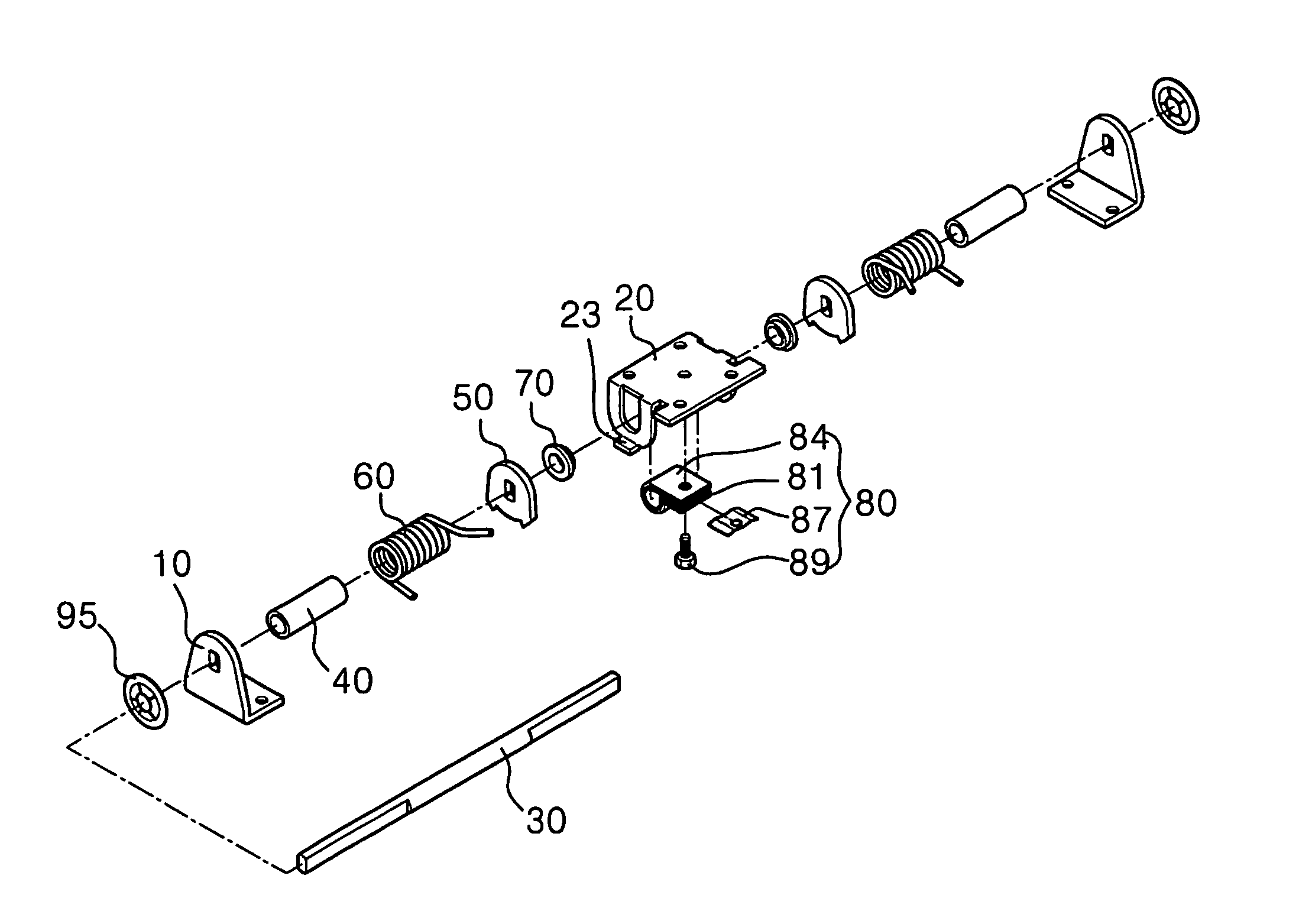
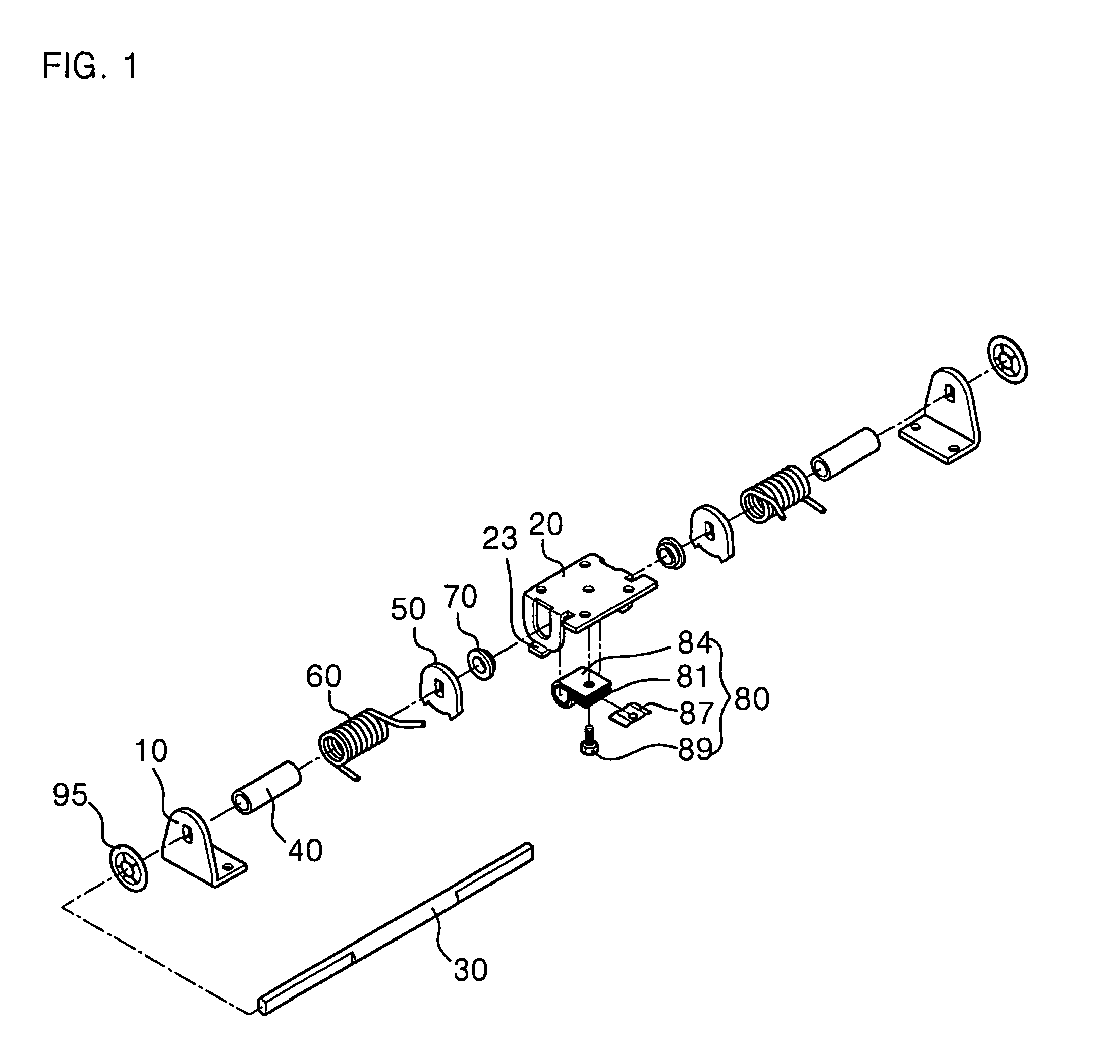
[0024]FIG. 1 is a perspective view of a hinge structure for a flat visual display device of the invention.

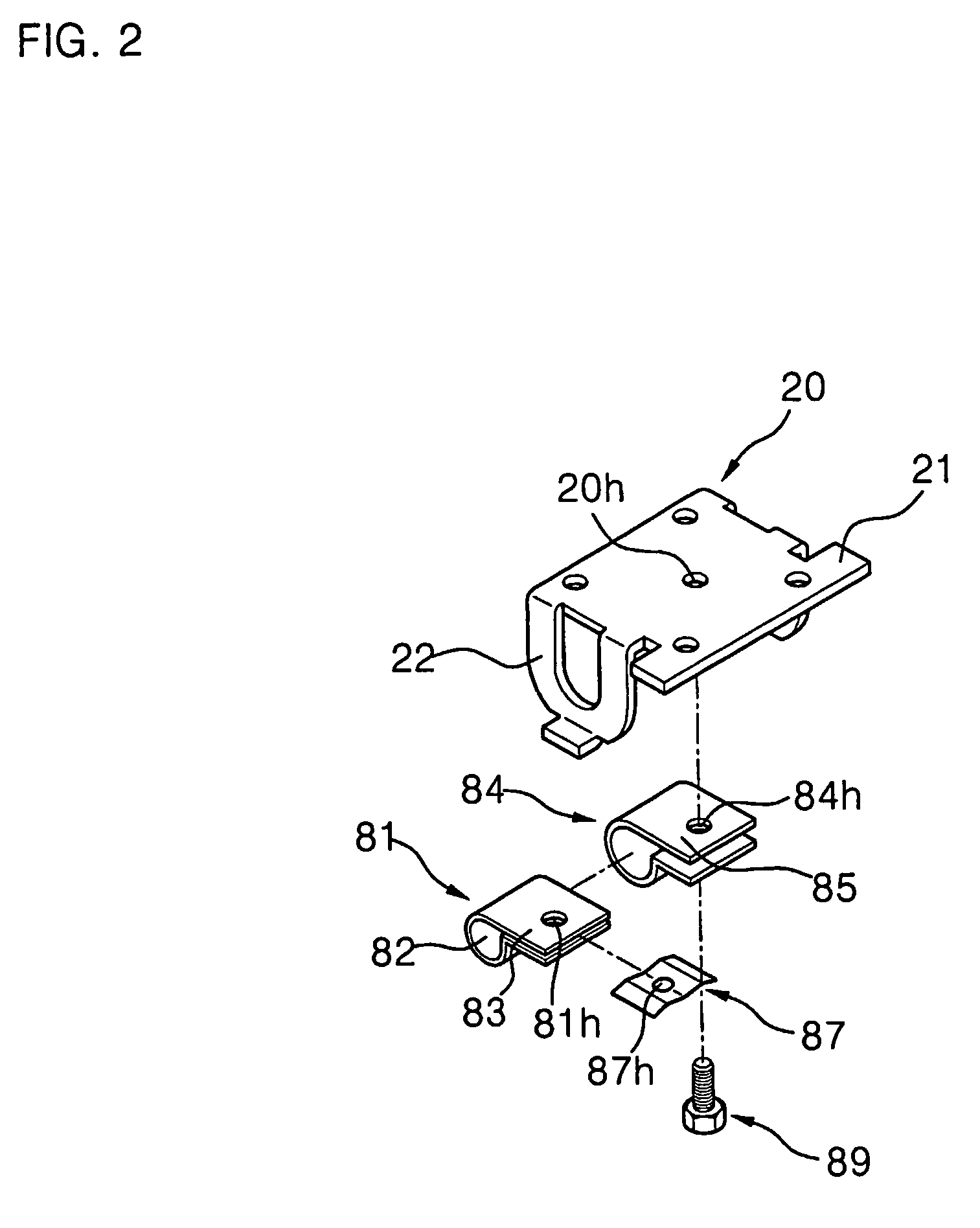
[0025]Describing the hinge structure of the invention as shown FIG. 1, the hinge structure has pivotal plates 10 for being mounted to a flat visual display device for vertically pivoting the same, a fixed plate 20 for being mounted to a supporting structure to which the flat visual display device will be supported for supporting the weight of the flat visual display device, a rotation shaft 30 inserted into vertical planes of the fixed and pivotal plates 20 and 10 facilitating vertical linear movement between the fixed and pivotal plates 20 and 10 with a certain degree of freedom, spacing members 40 fitted around the rotation shaft for maintaining gaps between the fixed plate 20 and the pivotal plates 10, elastic members 60...


PUM


Abstract

A hinge structure for a flat visual display device comprising: a fixed plate; pivotal plates; a rotation shaft inserted into vertical planes of the fixed and pivotal plates; rotation shaft-fixing ends in both ends of the rotation shaft for allowing the pivotal plates fitted around the ends of the rotation shaft to rotate together with the rotation shaft; a braking unit securely settled in the fixed plate and having a braking member for surrounding the outer circumference of the rotation shaft to generate braking force in the rotation shaft; stoppers folded from the fixed plate; stopper guides each having a guide groove in the outer circumference into which each of the stoppers is inserted and for being fitted around each of the rotation shaft-fixing ends; and a leaf spring inserted into a tightening face between both ends of the braking member.

Description

TECHNICAL FIELD[0001]The present invention relates to a hinge structure, and more particularly, to a hinge structure applicable to a flat visual display device and functioning as a structure between two members adopting a hinge so as to provide both of the members with smooth movement and braking force owing to a suitable amount of frictional force.BACKGROUND ART[0002]As well known in the art, a number of hinge structures are applied to move a pivoting member vertically or laterally in respect to a fixed member about one rotation shaft. More specifically describing an operation of an article to which the hinge structure is applied by way of illustration, this operation may include certain operations such as opening / closing of an article cover, opening / closing of an upper portion of a notebook computer and vertical adjustment of a visual display device. In particular, the invention relates to a hinge structure which can be more suitably applied to a flat visual display device.[0003]T...

Claims


Application Information

Patent Timeline
Patent Type & Authority Patents(United States)
IPC IPC(8): E05D11/10E05D11/08E05F1/12G06F1/16
CPCF16M11/10E05D11/082E05F1/1215E05Y2900/606Y10T16/5409Y10T16/54038Y10T16/54021Y10T16/54033Y10T16/5403F16M2200/041G06F1/16
Inventor LEE, GANG HOONJO, JAI HYUN
Owner LG ELECTRONICS INC
Why Eureka
Try Eureka