Locking pin locator

a technology of locking pins and locators, which is applied in the direction of convertible cycles, vehicles, and tractor-trailer combinations, can solve the problems of not revealing a signal capable of determining, the driver sitting in the tractor cannot see the relative position, and the weight limitations of steers, etc., and achieves the effect of reducing wear and tear

Active Publication Date: 2008-07-29
DIEHL ARNOLD WAYNE
View PDF17 Cites 12 Cited by
  • Summary
  • Abstract
  • Description
  • Claims
  • Application Information

AI Technical Summary

Benefits of technology

[0012]The unexpected recognition that the raised reinforcement plate located alongside a locking pin hole on the tandem axle rail can be used to turn on a signal available to the driver is the creative basis for the present invention. In the event that the reinforcement plate is attached to the inside of the tandem slide rail, the procedure must be reversed. The driver will calibrate the switch assembly at the desired hole location on the trailer slide rail until the signal is on and then slide the trailer until the ball / dome enters the hole at the locking pin and the pressure on the switch is released and signal is turned off. In this variation a rolling ball switch is preferred to reduce wear and tear when the ball moves along the tandem slide rail.

Problems solved by technology

Weight limitations apply to the steers, the drives and the tandems.
The difficulty of locating the trailer in the proper position over the tandems axle is that the driver sitting in the tractor cannot see the relative position of the trailer over the tandems at the back of the trailer.
It does not disclose a signal capable of determining when the locking pins are in position to engage selected holes in the trailer rail.
However it does so employing a much more complicated set of components.
The tool is not designed to signal the driver when the positioning pins are in position to be locked.

Method used


Image

  • Locking pin locator
  • Locking pin locator
  • Locking pin locator

Examples


Embodiment Construction

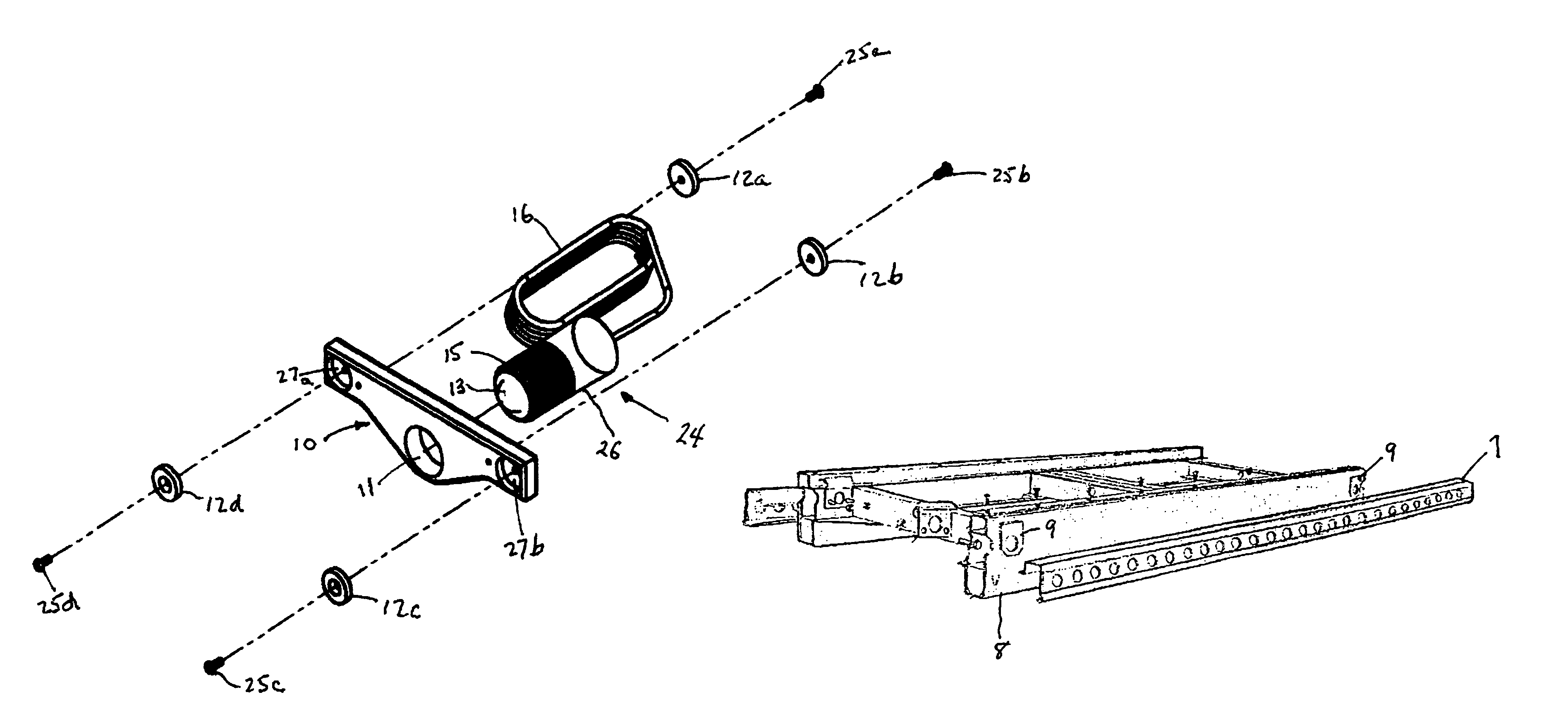
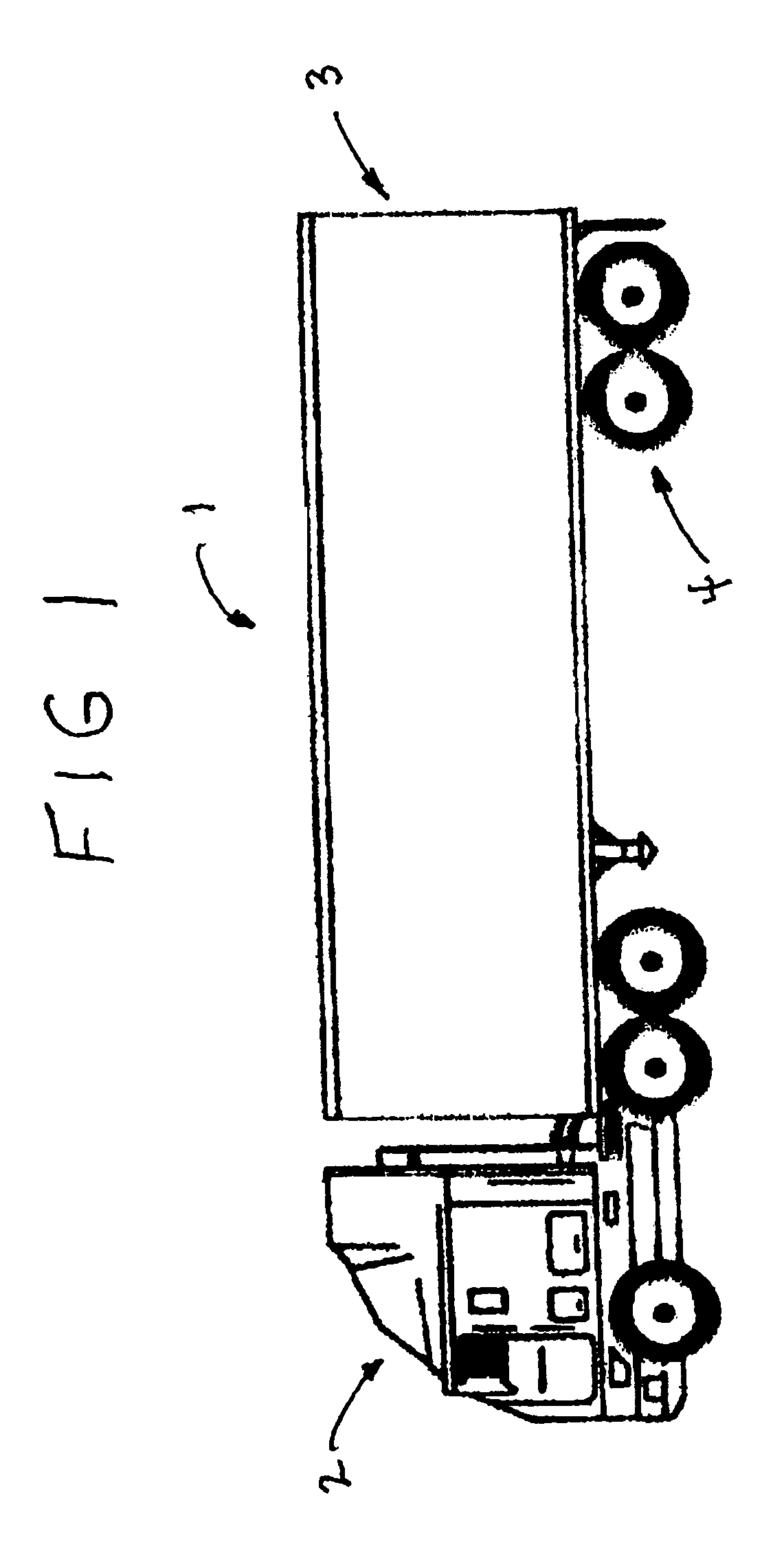
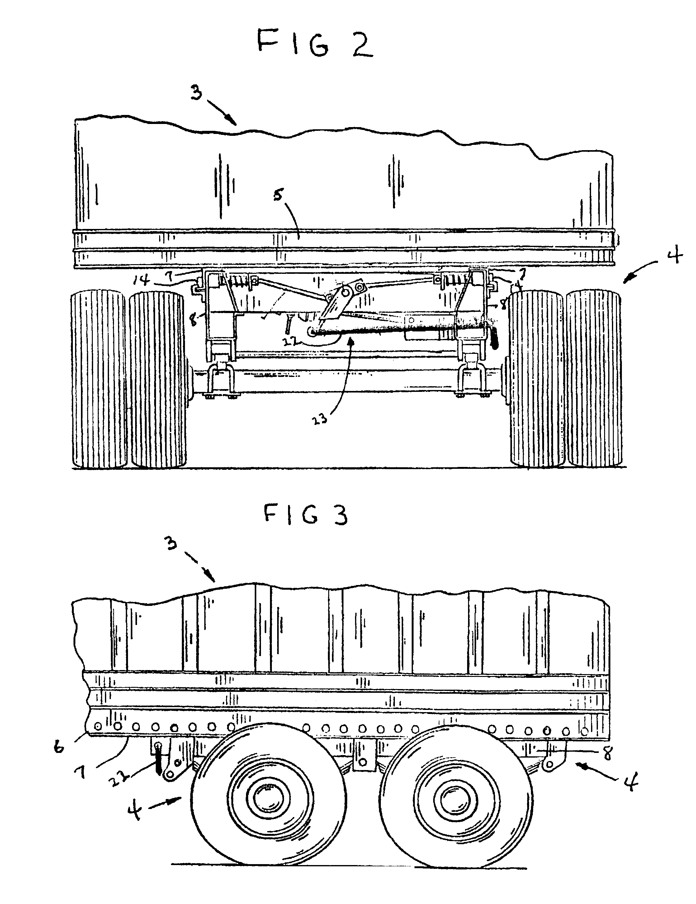
[0044]FIG. 1 pictures the basic components of a semi-truck 1, namely a tractor 2, a trailer 3 and a tandem axle 4. FIGS. 2 and 3 provide more detailed pictures of the back end of the trailer 3 coupled to the tandem axle 4 both from the front and the side as well as the mechanism 23 by which the pins are extended and retracted. FIGS. 2 and 3 are essentially reproductions of FIGS. 1 and 2 of U.S. Pat. No. 5,460,237 but omit details pertinent to the invention described and claimed in the patent. The patent also provides a more detailed description of the structure of the trailer and tandem axle and the means by which they are slidably connected employing matching pairs of slide rails and pins. The present invention is useful for trucks described in the patent albeit for a somewhat different purpose than the invention described and claimed in the patent. The invention of the patent helps to disconnect locking pins that are difficult to retract because of added friction brought about for...


PUM


Abstract

A compact, portable locking pin locator device adapted to assist the driver of a semi truck including a tractor and a trailer to locate the trailer over the tandem axle under the back end of the trailer to achieve proper weight and balance of the load carried in the trailer over the wheels of the truck.

Description

[0001]This invention relates to a portable locking pin locator device for use by the driver of a semi truck for locating the trailer of the truck in the proper position over the tandem axle under the trailer to achieve the correct and legal weight and balance relative to the different wheel locations of the truck, namely (a) the steering wheels (steers) located at the front of the tractor of the truck, (b) the driving wheels (drives) located at the rear of the tractor and (c) the tandem axle (tandems) located at the rear of the trailer.BACKGROUND OF THE INVENTION[0002]Semi trucks consist of a tractor and a trailer. For legal and safety concerns the loads carried in the trailers must meet state and federal weight requirements. This can be accomplished most often by positioning the trailer over the tandems in the rear of the trailer. Weight limitations apply to the steers, the drives and the tandems. Movement of the trailer over the tandems affects the weight at all three locations, t...

Claims


Application Information

Patent Timeline
Patent Type & Authority Patents(United States)
IPC IPC(8): B62D61/00
CPCB62D53/068
Inventor DIEHL, ARNOLD WAYNE
Owner DIEHL ARNOLD WAYNE
Why Eureka
Try Eureka