Modular energy absorber of varying topography and method for configuring same

a module energy absorber and topography technology, applied in the field of occupant safety, can solve the problems of presenting challenges to the recycling task, side collisions can be particularly deadly for infants, etc., and achieve the effect of cost effectiv

Inactive Publication Date: 2008-07-29
OAKWOOD ENERGY MANAGEMENT
View PDF8 Cites 68 Cited by
  • Summary
  • Abstract
  • Description
  • Claims
  • Application Information

AI Technical Summary

Benefits of technology

[0014]One object of the present invention is to provide a more cost effective, efficient energy absorber that can be “customized” or “tuned” to produce predefined energy absorption characteristics within spatial constraints that may be imposed by a particular application.

Problems solved by technology

Side collisions can be particularly deadly for infants, even if they are strapped in child seats.
Thus, the materials currently used may present challenges to the recycling task.

Method used


Image

  • Modular energy absorber of varying topography and method for configuring same
  • Modular energy absorber of varying topography and method for configuring same
  • Modular energy absorber of varying topography and method for configuring same

Examples


Embodiment Construction

)

1. The Energy Absorber

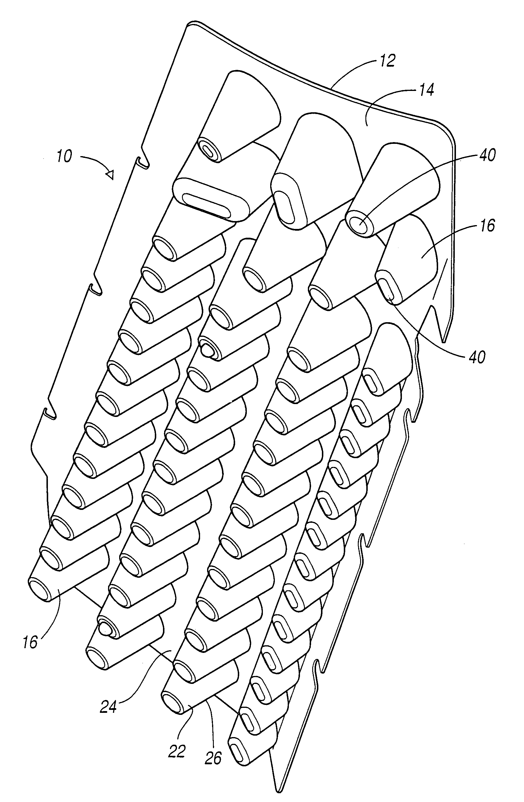
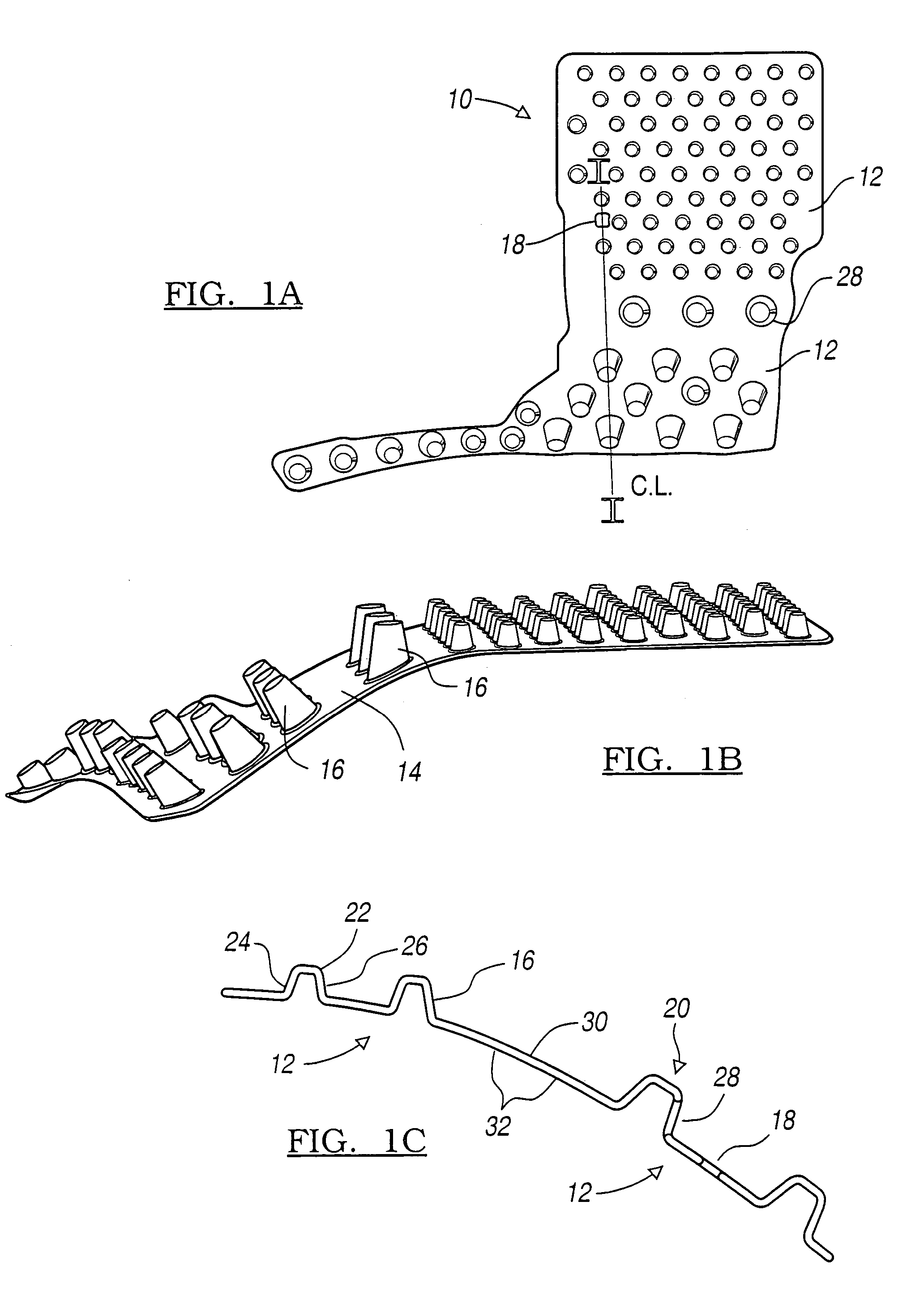
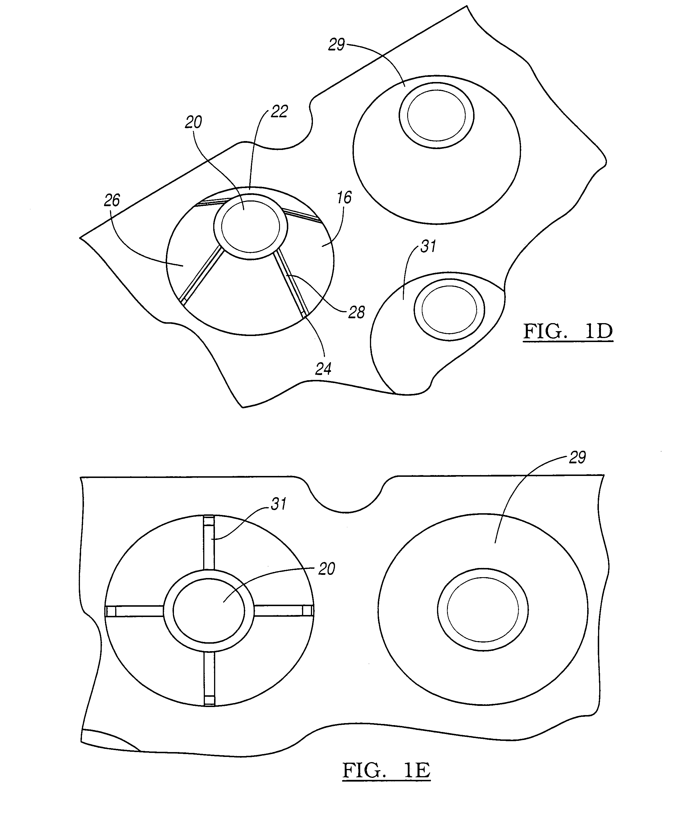
[0042]Turning first to FIGS. 1-2 of the drawings, there is depicted a modular energy absorber 10 that has one or more energy absorbing modules 12. The definition of the “energy absorbing module” which appears in the summary section of this application is incorporated here by reference.

[0043]Each module includes means 14 (FIG. 1(b)), such as a basal structure, for coordinating energy absorbing units 16 of a given energy absorbing module. The means for coordinating 14 has a topography that includes a number (n) of apertures 18 (note: regarding 18, that the drawing does not show a true through hole) defined therein, where n is an integer ≧o. The modular energy absorber 10 is characterized by energy absorbing units 16 that are connected by coordinating means 14 so that they give resistance and then buckle when impacted with sufficient force. In one embodiment, the energy absorbing units 16 take the form of truncated cones. The units are further characterized by ce...


PUM

PropertyMeasurementUnit
angleaaaaaaaaaa
heightsaaaaaaaaaa
thicknessaaaaaaaaaa

Abstract

A modular energy absorber 10 that is tunable. It comprises one or more energy absorbing modules 12. The energy absorbing modules have means for coordinating energy absorbing units 16 of the one or more modules. The means 14 for coordinating position and support the units in relation to each other before, during and after relative motion between an incident object and the energy absorber. A crushable member 16 is provided that has an upper perimeter 22, a lower perimeter 24 and an intermediate wall 26 extending therebetween. It also includes a number (m) of breaches defined therein before impact. A method for configuring the modular energy absorber is also disclosed.

Description

CROSS-REFERENCE TO RELATED APPLICATIONS[0001]This application is a continuation-in-part of U.S. application Ser. No. 10 / 760,760 filed Jan. 20, 2004, which is a continuation of U.S. application Ser. No. 10 / 004,739 filed Dec. 4, 2001 (now U.S. Pat. No. 6,752,450), which is a continuation-in-part of U.S. application Ser. No. 09 / 884,813 filed Jun. 19, 2001 (now U.S. Pat. No. 6,682,128) which is a continuation-in-part of U.S. application Ser. No. 09 / 499,205 filed Feb. 7, 2000 (now U.S. Pat. No. 6,247,745), the disclosures of which applications are being incorporated by reference herein. Application Ser. No. 10 / 760,760 is also a continuation-in-part of U.S. application Ser. No. 09 / 617,691 filed Jul. 17, 2000 (now U.S. Pat. No. 6,679,967), the disclosure of which application is being incorporated by reference herein.BACKGROUND OF THE INVENTION[0002]1. Field of the Invention[0003]This invention generally relates to occupant safety during a collision, and more specifically to a “customized” ...

Claims


Application Information

Patent Timeline
Patent Type & Authority Patents(United States)
IPC IPC(8): B60R21/04B60R99/00A62B1/22B29C51/10B29C51/12B29C51/14B32B3/28B60N2/42B60N2/70B60R19/18B60R19/34B65D81/127F16F1/376F16F7/12
CPCA62B1/22B29C51/10B29C51/12B29C51/14B29C2791/006B29C2791/007B29L2009/00B29L2031/3044B29L2031/721B32B3/28B60N2/4249B60N2/70B60R19/18B60R19/34B60R21/04B60R21/0428B60R2019/1846B60R2019/1866B60R2021/0414B60R2021/0421B60R2021/0435B60R2021/0442B65D81/127F16F1/376F16F7/121B60R13/02
Inventor CORMIER, JOEL MATTHEWAUDI, RICHARD FRANCOIS
Owner OAKWOOD ENERGY MANAGEMENT
Why Eureka
Try Eureka