Scroll fluid machine having oil-supply holes being formed through a reinforcement bearing plate on a rear surface of the orbiting scroll

a technology of rotating fluid machine and reinforcement bearing plate, which is applied in the direction of machines/engines, rotary/oscillating piston pump components, liquid fuel engines, etc., can solve the problems of reducing efficiency, noise, heat or vibration, and the tip seal of the fixed scroll is unlikely to wear, and achieves the effect of easy supply

Inactive Publication Date: 2008-07-29
ANEST IWATA CORP
View PDF8 Cites 49 Cited by
  • Summary
  • Abstract
  • Description
  • Claims
  • Application Information

AI Technical Summary

Benefits of technology

[0009]In view of the disadvantages in the prior art, it is an object of the invention to provide a scroll fluid machine in which an orbiting end plate is made as thin as possible to prevent an orbiting wrap from becoming nonuniform or being deformed locally owing to difference in cooling speed of each part after casting when made of Al metal by die casting and preventing the orbiting end plate from curving or being deformed locally owing to differences in heat and pressure strength during operation, oil being easily supplied into bearings.

Problems solved by technology

Thus, each surface of the orbiting end plate is unlikely to stretch locally or be curved to prevent unsmoothing in operation or decrease in efficiency, or the tip seal of the fixed scroll is unlikely to wear unequally to prevent performance from decreasing or prevent vibration or noise.
However, as described in JP7-42953B2, in the orbiting scroll having the orbiting wrap only on one surface, a bearing boss projects on the rear surface of the orbiting end plate, so that the orbiting end plate is unequally deformed or stretched or causes angles of the orbiting wrap to differ locally owing to pressure load, friction with the tip seal of the fixed scroll or unequality on generated heat.
Thus, the orbiting wrap contacts the fixed end plate with deviation to cause variation in pressure locally reducing efficiency or involving noise, heat or vibration.
Furthermore, the tip seals of the fixed and orbiting scrolls locally wears to decrease duration.
With large thickness of the orbiting end plate, during cooling after die casting, cooling speed of the orbiting end plate and orbiting wrap becomes nonuniform, so that the angle of the orbiting wrap becomes different locally to decrease efficiency thereby speeding up wear or causing noise.
It is necessary to provide a supply hole for grease for each of the bearings horizontally, and it is troublesome for the grease to put in the bearing via the holes.

Method used


Image

  • Scroll fluid machine having oil-supply holes being formed through a reinforcement bearing plate on a rear surface of the orbiting scroll
  • Scroll fluid machine having oil-supply holes being formed through a reinforcement bearing plate on a rear surface of the orbiting scroll
  • Scroll fluid machine having oil-supply holes being formed through a reinforcement bearing plate on a rear surface of the orbiting scroll

Examples


first embodiment

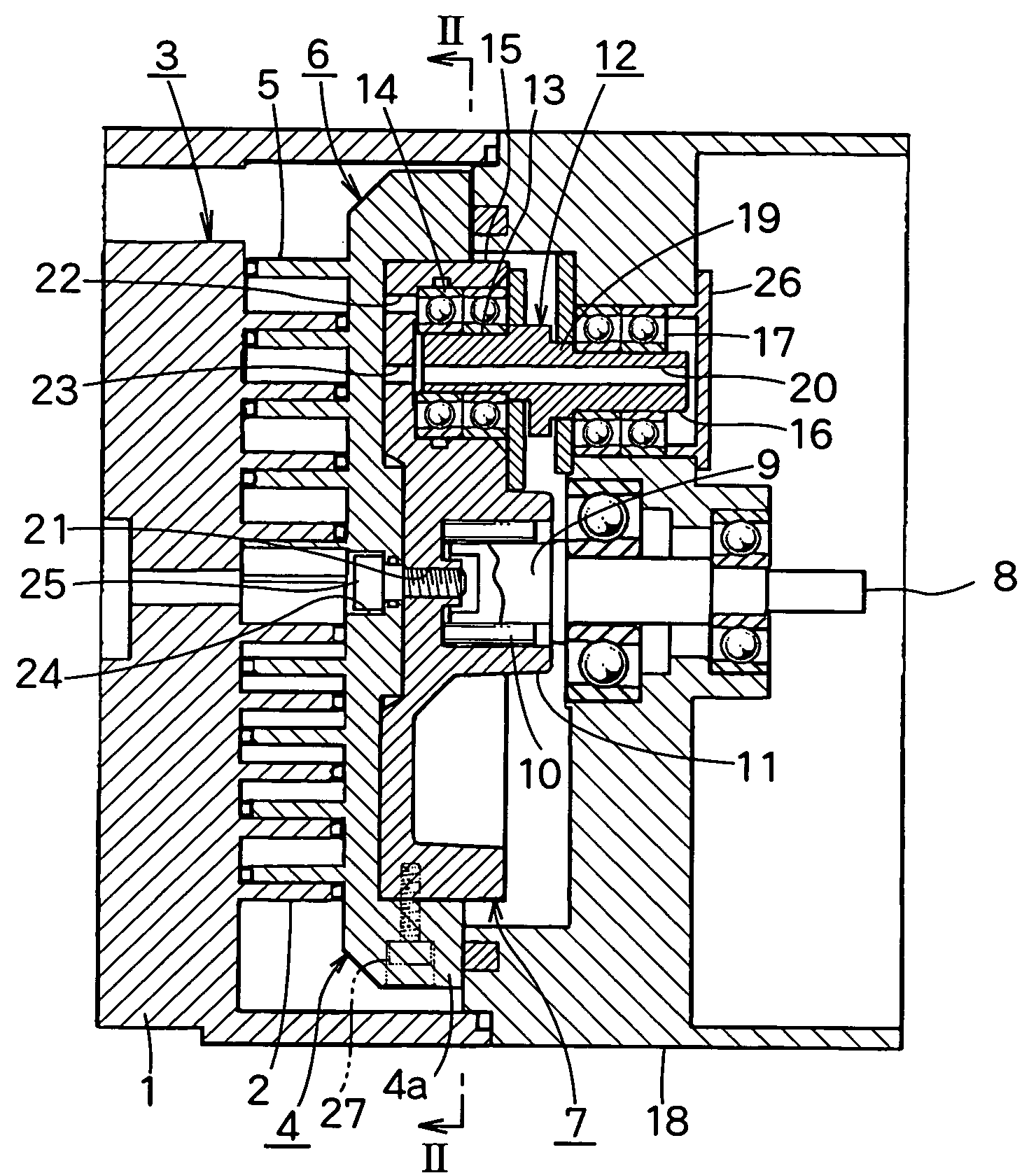
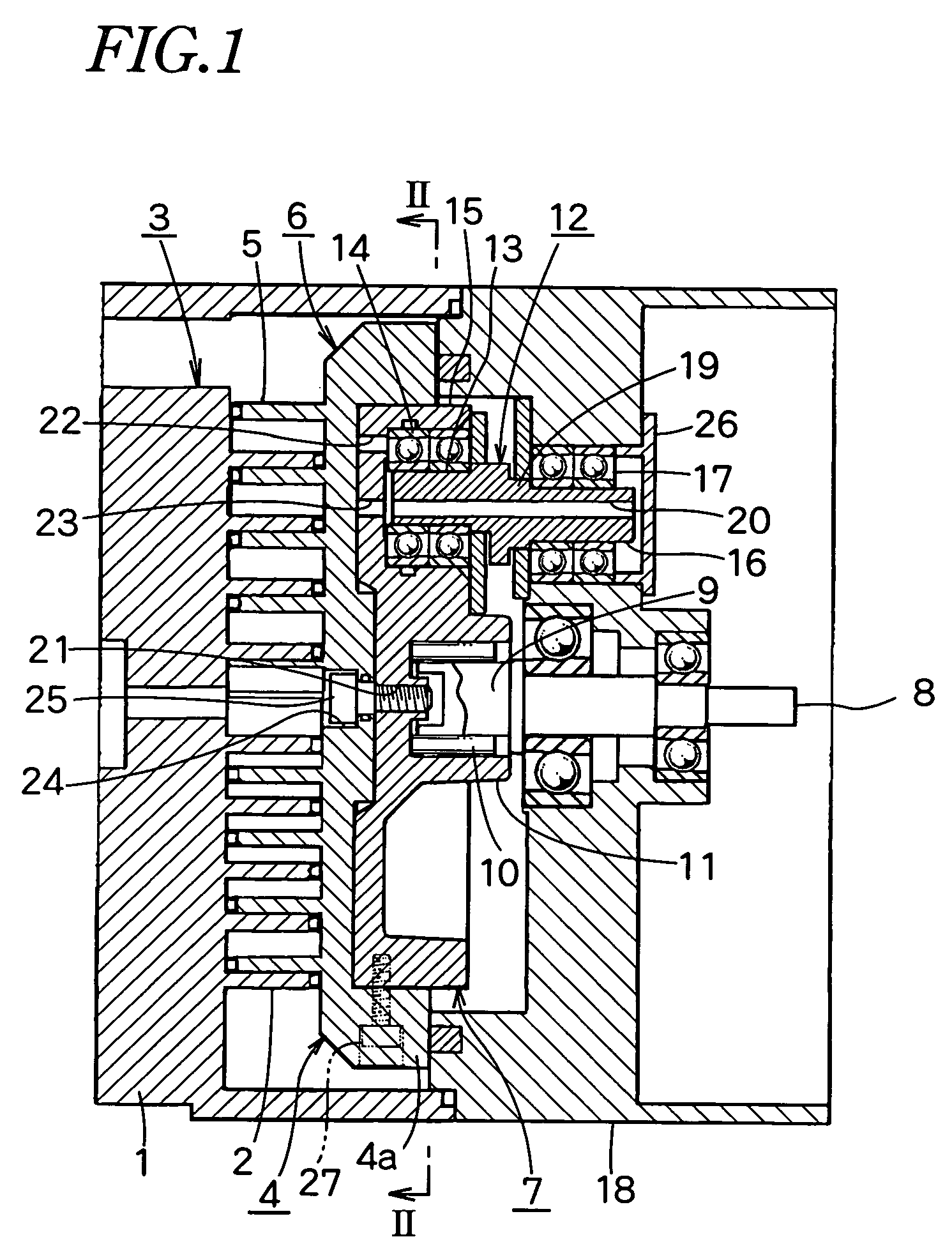
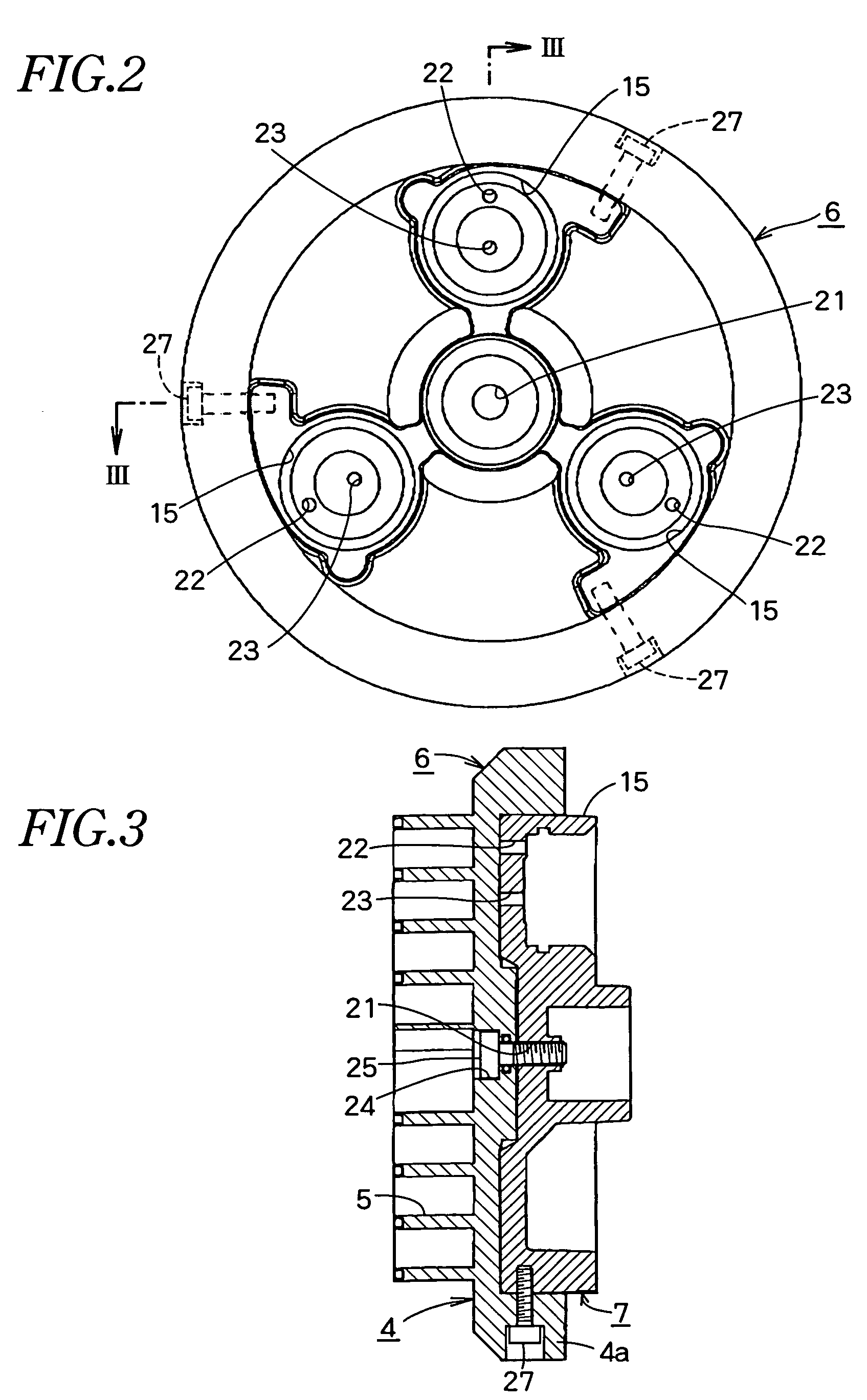
[0017]FIG. 1 is a vertical sectional side view of a scroll fluid machine according to the present invention. FIG. 2 is a vertical sectional view taken along the line II-II in FIG. 1 in which a driving shaft and a self-rotation preventing device are removed. FIG. 3 is a sectional view taken along the line III-III in FIG. 2.

[0018]As shown in FIG. 1, the scroll fluid machine comprises a fixed scroll 3 which comprises a fixed end plate 1 having a spiral fixed wrap 2 on the rear surface, and an orbiting scroll 6 which comprises an orbiting end plate 4 having an orbiting wrap 5 on the front surface to allow the fixed wrap 2 to engage with the orbiting wrap 5.

[0019]The orbiting end plate 4 has a thick annular flange 4a and a reinforcement bearing plate 7 engaged in the annular flange 4a is placed on the rear surface of the orbiting end plate 4.

[0020]On the center of the rear surface of the reinforcement bearing plate 7, a bearing tube 11 projects to support an eccentric axial portion 9 of ...

second embodiment

[0027]FIG. 4 shows the present invention and is similar to FIG. 3. The same numerals are allotted to the same members and only differences will be described.

[0028]An annular flange 7a of a reinforcement bearing plate 7 is fitted in an annular flange 4a circumferentially formed on an orbiting end plate 4. A bolt 28 is inserted from the outer corner of the front surface of the annular flange 4a inwards and rearwards and screwed in the annular flange 7a of the reinforcement bearing plate 7.

third embodiment

[0029]FIG. 5 is the present invention and similar to FIG. 3. The same numerals are allotted to the same members and differences are only described.

[0030]An orbiting end plate 4 having no annular flange is fitted on a reinforcement bearing plate 7 having no annular flange, and they are fixed to each other with a bolt 29 passing through the outer circumferences obliquely.


PUM


Abstract

A scroll fluid machine comprises a fixed scroll, an orbiting scroll and a plurality of self-rotation preventing device for preventing the orbiting scroll from rotating on its own axis. On the rear surface of the orbiting scroll, a reinforcement bearing plate is fixed with a central bolt and an outer circumferential bolt. A follower of the self-rotation preventing device is provided in the reinforcement bearing plate. An oil-supply hole is formed through the reinforcement bearing plate to supply oil to the follower.

Description

[0001]This application claims priority from Japanese Application Serial No. 2005-324114 filed Nov. 8, 2005.BACKGROUND OF THE INVENTION[0002]The present invention relates to a scroll fluid machine and particularly to a scroll fluid machine in which a fixed wrap of a fixed scroll in a housing engages with an orbiting wrap of an orbiting scroll rotatably mounted around an eccentric axial portion of a driving shaft, the orbiting scroll being eccentrically revolved with the driving shaft so that a gas sucked from the circumference or center of the housing is compressed or expanded towards the center or circumference.[0003]JP2004-308436A discloses a scroll fluid machine having an orbiting scroll comprising an orbiting end plate having an orbiting wrap on each surface, and JP7-42953B2 discloses a scroll fluid machine in which an orbiting wrap projects on only one surface of an orbiting end plate.[0004]In the former, during operation, a tip seal on the top of the fixed wrap of the fixed scr...

Claims


Application Information

Patent Timeline
Patent Type & Authority Patents(United States)
IPC IPC(8): F03C2/00F04C18/00
CPCF04C18/0253F04C29/028F04C29/0057F04C2240/805F04C2240/603F04C18/02F04C29/02
Inventor ISHIKAWA, HIDETOSHITSUCHIYA, MASARU
Owner ANEST IWATA CORP
Why Eureka
Try Eureka