
Electro mechanical connector for use in electrical applications

Active Publication Date: 2008-07-29
TESLA INC
View PDF3 Cites 61 Cited by
  • Summary
  • Abstract
  • Description
  • Claims
  • Application Information

AI Technical Summary

Benefits of technology

[0014]Still another advantage of the present invention may be to provide an electrical connector that allows signaling electrically to inline contactors in advance of the minimum insertion condition of the power pins to provide an effective hot disconnect using contacts not normally intended for breaking under electrical load.
[0015]To achieve the foregoing objects, an electrical connector having a mechanical actuator and locking mechanism is disclosed. The electrical connector includes a locking collar having a slot therein. The connector also includes a plug body arranged within the locking collar and a switch mount sleeve arranged over the plug body. The electrical connector has a micro switch connected to the switch mount sleeve and a switch actuator slidingly arranged within the slot of the locking collar.
[0016]One advantage of the present invention may be that it provides a novel and improved electrical connector for use in an electric vehicle or other industrial equipment.
[0017]Still a further advantage of the present invention may be that it provides for an electro mechanical connector for use in an electrical vehicle or other industrial applications that allows for a disconnect of a connector that is under electric load when the motion is initiated without having to use contacts that have been designed to withstand the arcing that occurs when a power contact separates.
[0018]Another advantage of the present invention may be that it provides a means to remotely determine if the connector is mated and locked before any unsafe voltages are applied to an electrical connector.
[0019]Still another advantage of the present invention may be that it creates a longer effective length difference between a last mate first break contact pair and the other contacts in a connector without adding additional length to the connector body.

Problems solved by technology

However, many of these prior art systems have problems in guaranteeing that the connector is locked into its appropriate position, nor do they allow for an independent motion to change the timing between the separation of the first break contact and the second break and thereafter contacts or pins.

Method used


Image

  • Electro mechanical connector for use in electrical applications
  • Electro mechanical connector for use in electrical applications
  • Electro mechanical connector for use in electrical applications

Examples


Embodiment Construction

)

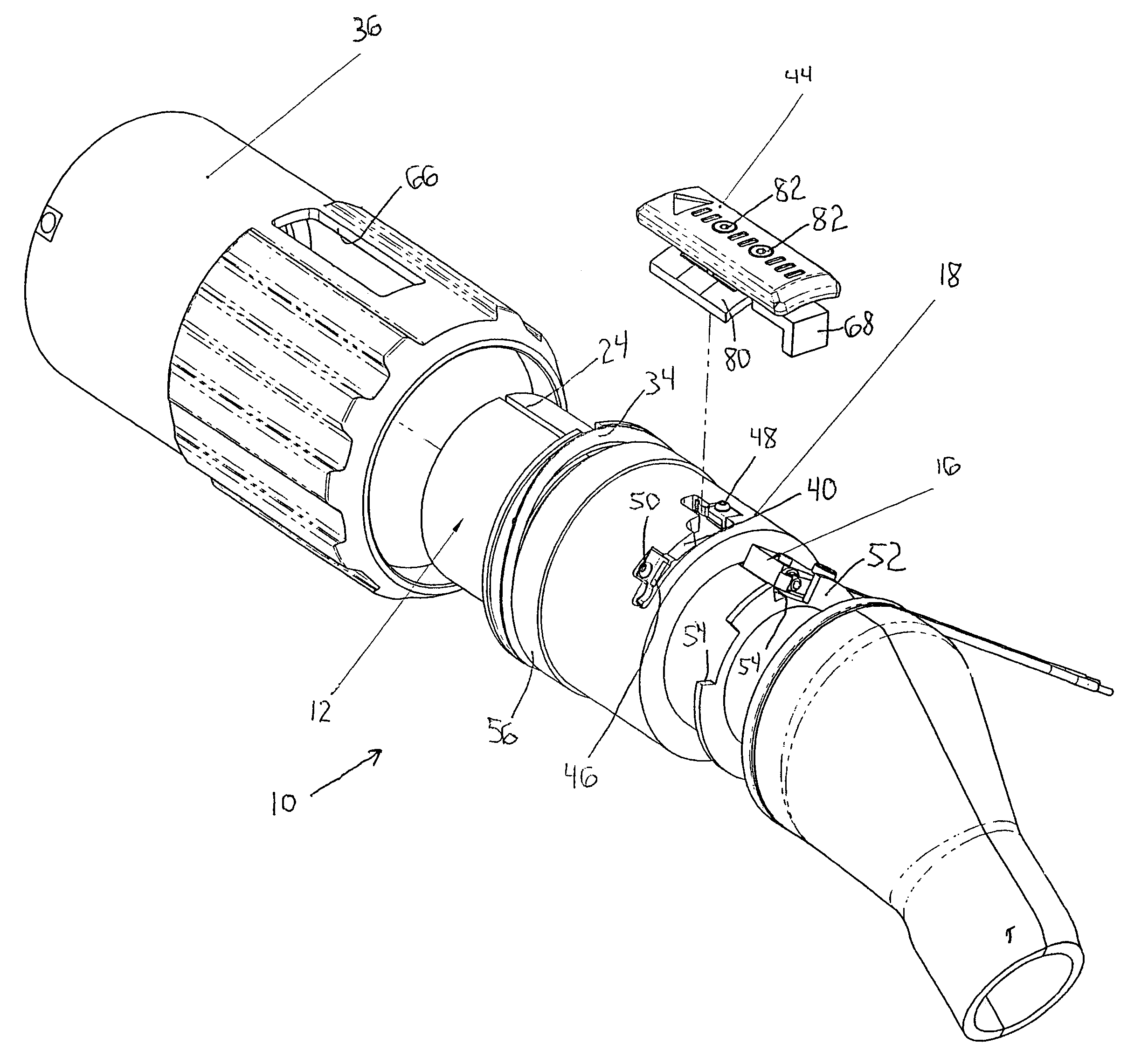
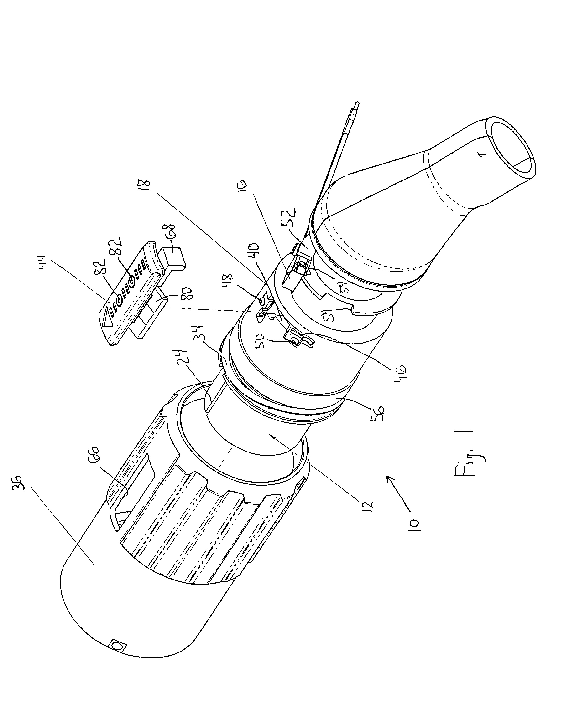
[0034]Referring to the drawings, an electrical connector 10 for use in an electrical vehicle or other industrial equipment or applications is shown. It should be noted that the electrical connector 10 shown in the drawings is for use in an electrical vehicle, however the electrical connector 10 may be used in any combination and in any known design in any number of industries, including but not limited to, any type of vehicle, and any technology dealing with aerospace, marine, aviation, industrial equipment, and any other electrical system that has a need for high or low voltage electrical connectors for use in connecting electrical circuits and / or charging battery systems within components or vehicles. The connector 10 of the present invention will be able to lock such that it will provide a controlled time delay on the first break pin of a FMLB configuration within the plug body. The electrical connector 10 will also provide an electrical means to determine that the connector 10 ...


PUM


Abstract

An electro mechanical connector for use in an electrical vehicle having a battery pack is disclosed. The connector includes a locking collar having a slot therein and a plug body arranged within the locking collar. The connector also has a switch mount sleeve arranged on the plug body and a micro switch connected to the switch mount sleeve at a predetermined position. The electrical connector also includes a switch actuator that is slidingly arranged within the slot and is aligned with the micro switch when the electrical mechanical connector is in its fully locked position.

Description

BACKGROUND OF THE INVENTION[0001]1. Field of the Invention[0002]The subject invention generally relates to electro mechanical connectors for electrical circuits, and more particularly relates to an electro mechanical connector having a lock to control time delay on a first break pin and provide an electrical means to determine the locking state of the connector.[0003]2. Description of Related Art[0004]Electrical connectors have been known for numerous years. Many of these electrical connectors use a first mate last break (FMLB) configuration. The FMLB configuration will allow for a timing difference between electrical continuity of any two contact pairs in a connector body. Generally, in these prior art FMLB configurations two contacts of different lengths are installed within a connector body such that the shortest contact does not make a connection until after the longer contact is partially engaged. This will allow for a timing difference between the electrical continuity of the ...

Claims


Application Information

Patent Timeline
IPC IPC(8): H01R13/44
CPCH01R13/701H01R13/7036B60L11/1818Y02T90/14B60L2270/34Y02T10/7005B60L2270/32Y02T10/7072B60L53/16Y02T10/70
Inventor FREY, PAUL DEWITTLU, DAVID TSE-ZHOULYONS, II, DAVID FREDERICK
Owner TESLA INC
Features
  • Generate Ideas
  • Intellectual Property
  • Life Sciences
  • Materials
  • Tech Scout
  • Unparalleled Data Quality
  • Higher Quality Content
  • 60% Fewer Hallucinations
Learn More