Bow sighting device

a sighting device and bow technology, applied in the field of sighting devices, can solve the problems of reduced complexity of bow hunting equipment compared to gun hunting equipment, lost arrows or wounded (not killed) game, and difficulty in sighting a compound bow during hunting or sighting a crossbow prior to an actual hunt, and achieve the effect of simplifying hunting

Inactive Publication Date: 2008-08-12
JONES JAMES A
View PDF11 Cites 20 Cited by
  • Summary
  • Abstract
  • Description
  • Claims
  • Application Information

AI Technical Summary

Benefits of technology

[0011]Yet another object of the present invention is to provide a bow sighting device, as aforesaid, which may focus the laser beam on a single point or split the beam into multiple beams.
[0013]A still further object of the present invention is to provide a bow sighting device, as aforesaid, that simplifies hunting with a compound bow, recurve bow, or crossbow.

Problems solved by technology

One reason that more deer hunters do not use compound bows may be the relative complexity of bow hunting equipment as compared to gun hunting equipment.
Another reason most deer hunters prefer to use guns is that shots taken with bows often miss their targets, resulting in lost arrows or wounded (not killed) game.
Sighting a compound bow during hunting or sighting a crossbow prior to an actual hunt can be a difficult endeavor.
Crossbows, and more particularly their targeting scopes, may also be “sighted in” by adjusting windage and elevation settings such that the hunter can achieve greater accuracy during a hunt although this is often a trial and error task.
Although the prior devices and proposals are assumably effective for their intended purposes, the existing devices do not provide a virtually guaranteed means for targeting and hitting a deer or a sighting target.

Method used


Image

  • Bow sighting device
  • Bow sighting device
  • Bow sighting device

Examples


Embodiment Construction

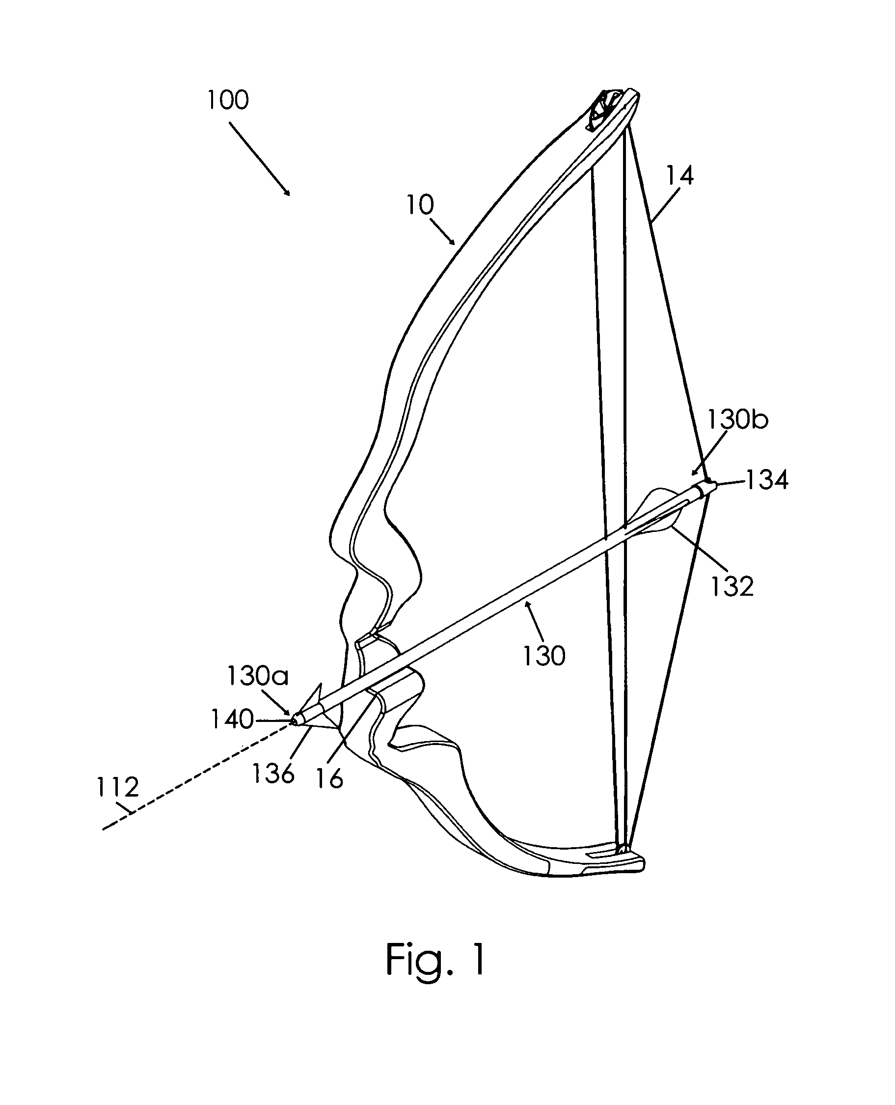
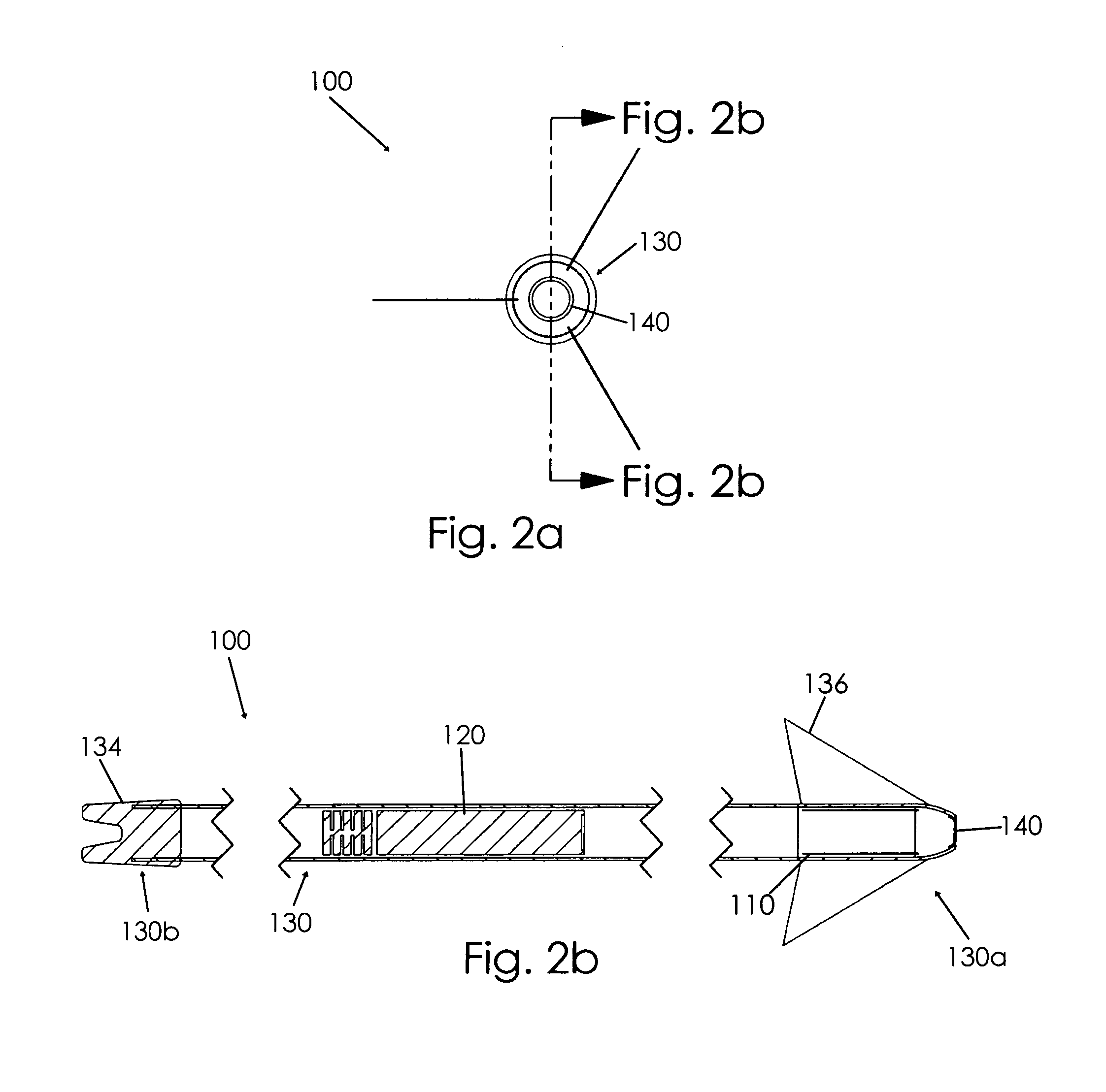
[0030]A bow sighting device 100 according to the present invention will now be described in detail with reference to FIGS. 1 through 2b and FIGS. 5 through 7 of the accompanying drawings. More particularly, a bow sighting device 100 according to the current invention includes a laser 110, a power source 120, and an arrow shaft 130.

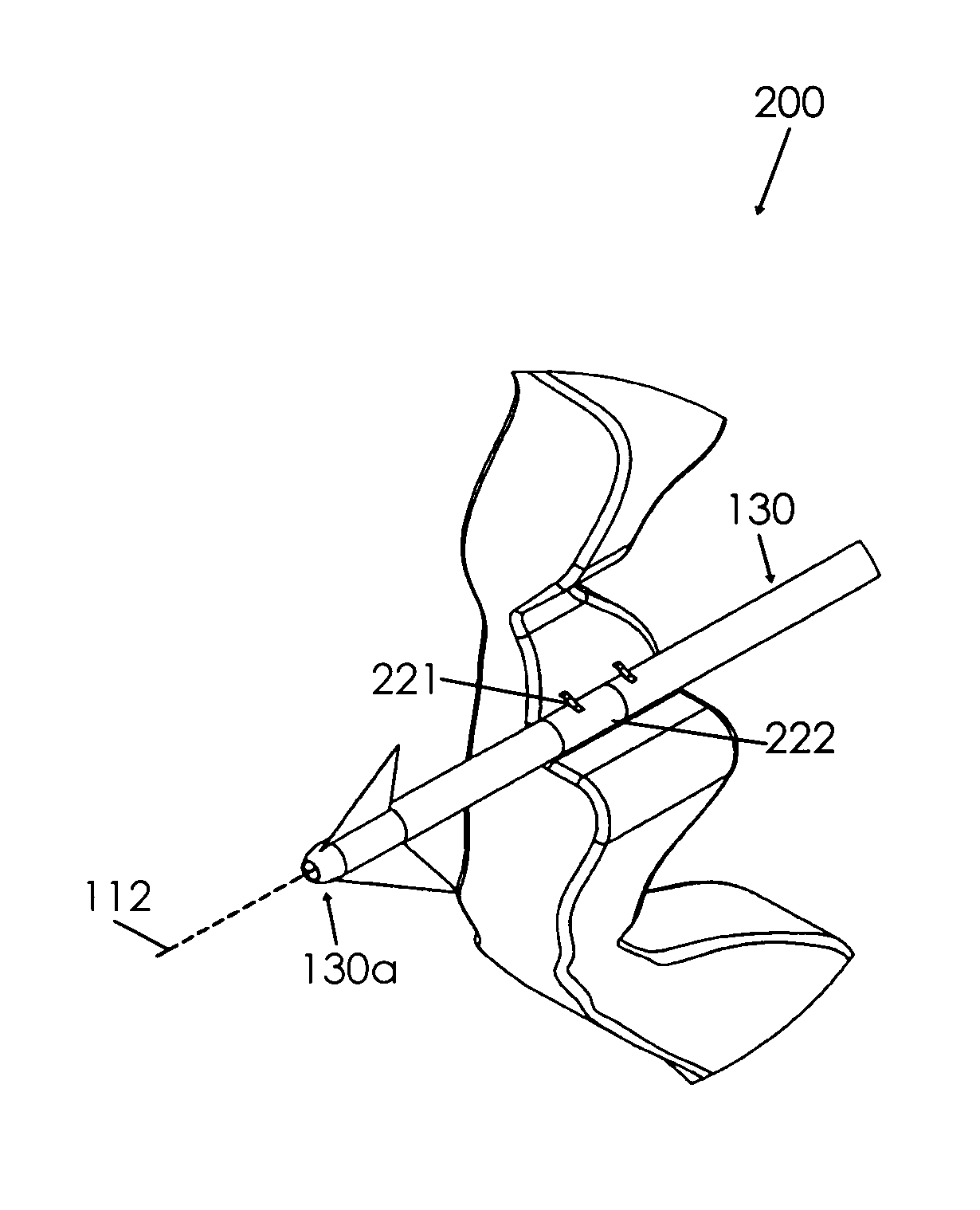
[0031]The laser 110 is in electrical communication with the power source 120 to actuate the laser 110. When actuated, the laser 110 produces a laser beam 112. The arrow shaft 130 has forward and rear ends 130a, 130b, and the laser beam 112 extends / projects from the shaft forward end 130a away from the shaft rear end 130b (FIG. 1). As best shown in FIG. 7, the laser beam 112 may extend from within the arrow shaft 130 through the shaft forward end 130a. The arrow shaft 130 may include fletching 132 at the shaft rear end 130b, a nock 134 at the shaft rear end 130b, and / or an arrowhead 136 at the shaft forward end 130a (FIG. 1).

[0032]It is understood that the ...


PUM


Abstract

A bow sighting device according to the present invention includes a laser in electrical communication with a power source to actuate the laser to produce a laser beam. The bow sighting device includes an arrow shaft having forward and rear ends with the laser positioned in the arrow shaft such that the laser beam projects through the forward end. A focusing lens may be positioned at the forward end through which the laser beam passes. The sighting device may include a nock at the rear end and a pushrod configured such that the pushrod urges the power source into connection with the laser when the arrow shaft is placed in ready-to-fire configuration relative to the bow. The bow sighting device simplifies hunting with a compound bow or crossbow by providing a visual indication of exactly where the arrow shaft is aimed.

Description

BACKGROUND OF THE INVENTION[0001]This invention relates generally to sighting devices and, more particularly, to a bow sighting device for focusing laser light on a target utilizing a laser mounted inside or outside of an arrow shaft.[0002]In 2004, there were 14,283,920 deer hunters in the United States according to the Deer Hunter's Almanac. Of these, 3,183,643 were archery hunters. One reason that more deer hunters do not use compound bows may be the relative complexity of bow hunting equipment as compared to gun hunting equipment. Another reason most deer hunters prefer to use guns is that shots taken with bows often miss their targets, resulting in lost arrows or wounded (not killed) game. Sighting a compound bow during hunting or sighting a crossbow prior to an actual hunt can be a difficult endeavor.[0003]Various devices have been proposed in the art for aiding a bow hunter in sighting or targeting a hunted animal. Sighting accessories may be mounted to the frame or strings of...

Claims


Application Information

Patent Timeline
Patent Type & Authority Patents(United States)
IPC IPC(8): F41G1/467
CPCF41G1/35F42B12/362F42B6/04F41G1/467
Inventor JONES, JAMES A.
Owner JONES JAMES A
Why Eureka
Try Eureka