Pressure sensor

a technology of pressure sensor and pressure sensor, which is applied in the direction of fluid pressure measurement, fluid pressure measurement by electric/magnetic elements, instruments, etc., can solve the problems of not being very accurate, the accuracy of tank monitors that use fluid pressure is much more accurate, and the cost is high

Inactive Publication Date: 2008-08-12
SENSATA TECHNOLOGIES INC
View PDF19 Cites 42 Cited by
  • Summary
  • Abstract
  • Description
  • Claims
  • Application Information

AI Technical Summary

Benefits of technology

[0009]The processor may monitor a reference electrical signal from each of the at least two optical receivers, wherein a difference between the electrical signals is representative of the pressure change. Further, the processor may compensate for variations in aging, temperature, and quality of the optical transmitter and the receivers.

Problems solved by technology

Although resistive tank sensors are inexpensive, they are not very accurate.
Tank monitors that use fluid pressure are much more accurate, but much more expensive as well.

Method used


Image

  • Pressure sensor
  • Pressure sensor
  • Pressure sensor

Examples


Embodiment Construction

[0022]The present invention will now be described more fully hereinafter with reference to the accompanying drawings, in which preferred embodiments of the invention are shown. This invention may, however, be embodied in many different forms and should not be construed as limited to the embodiments set forth herein. Rather, these embodiments are provided so that this disclosure will be thorough and complete, and will fully convey the scope of the invention to those skilled in the art. Like numbers refer to like elements throughout, and prime notation is used to indicate similar elements in alternate embodiments.

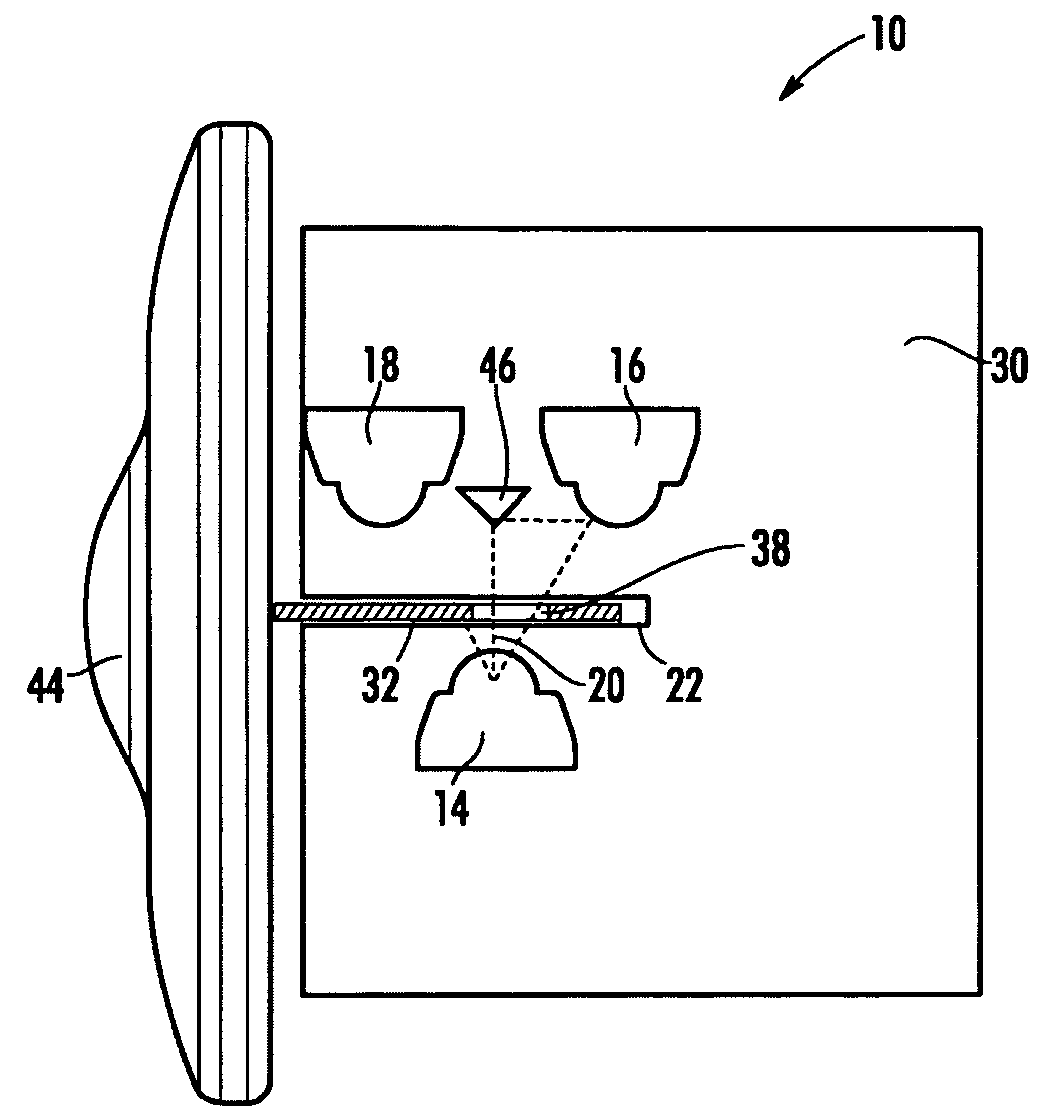
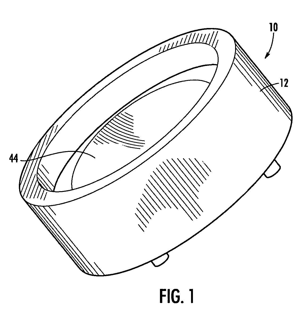
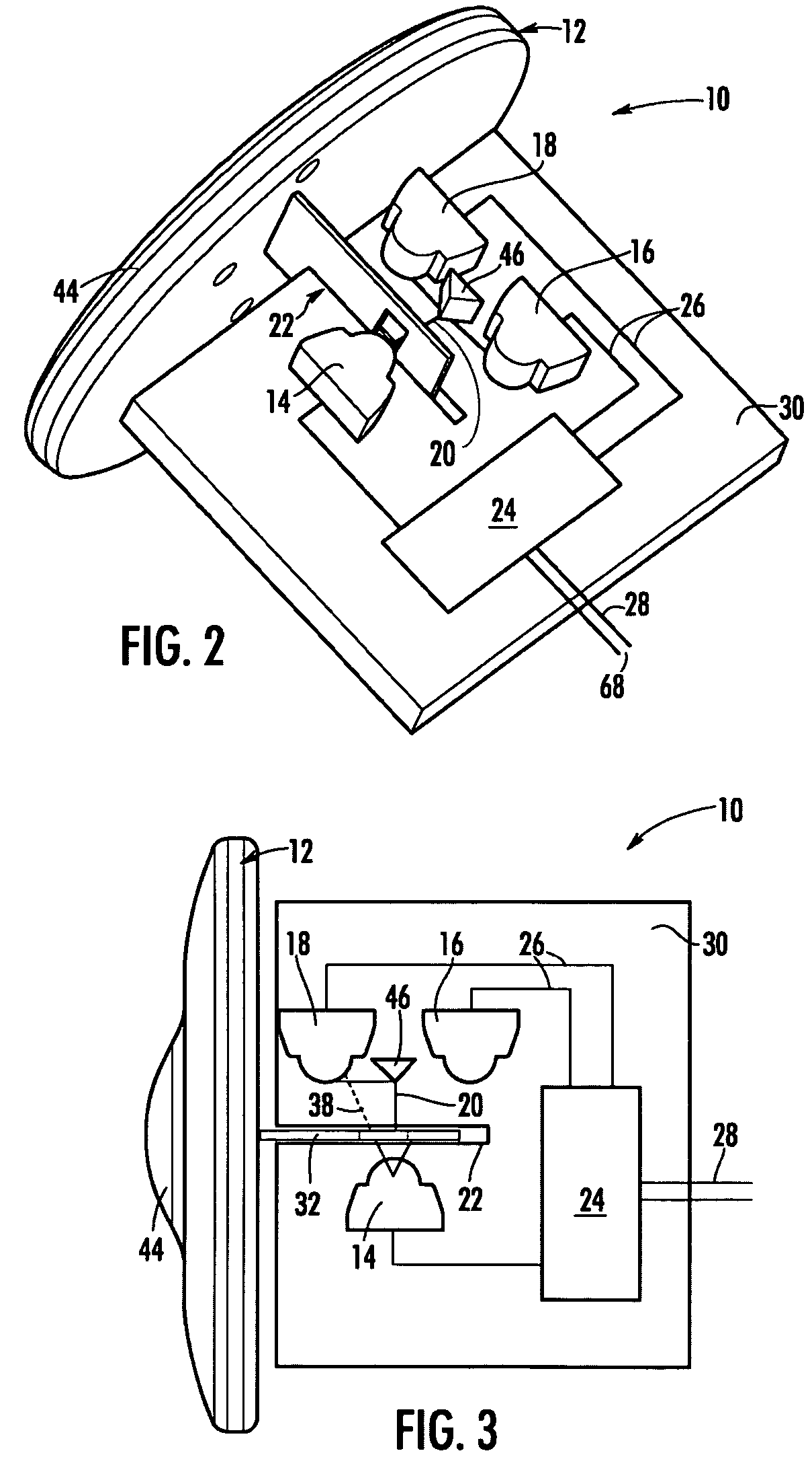
[0023]Referring initially to FIGS. 1 and 2, a pressure sensor 10 in keeping with the teachings of the present invention comprises a housing 12 includes an optical transmitter 14 and at least two optical receivers, herein referred to as a positive receiver 16 and a negative receiver 18 carried inside the housing. The optical transmitter 14 is positioned for emitting light in a...


PUM

PropertyMeasurementUnit
angle of divergenceaaaaaaaaaa
pressureaaaaaaaaaa
angular reflectionaaaaaaaaaa

Abstract

A pressure sensor includes an optical transmitter transmitting a dispersive light toward two optical receivers, all carried in a housing. Pressure changes on the housing cause the light beam to be deflected with the amount of deflection measured by the difference in light received by each of the two receivers. A processor operable with the receivers provides a pressure measurement responsive to the light beam deflection.

Description

CROSS-REFERENCE TO RELATED APPLICATIONS[0001]This application claims the benefit of U.S. Provisional Application No. 60 / 616,456, filed Oct. 5, 2004 and U.S. Provisional Application No. 60 / 616,460, filed Oct. 5, 2004, each for a “Pressure Sensor,” the disclosures of which are hereby incorporated by reference herein in their entireties and all commonly owned.FIELD OF THE INVENTION[0002]The present invention generally relates to pressure sensors and in particular to a pressure sensor measuring changes in pressure through changes in light beam deflection.BACKGROUND OF THE INVENTION[0003]Typical inexpensive pressure sensing systems are of the resistive type. By way of example, a resistive tank pressure sensor may use a floater that changes the output resistance if the tank level either rises or lowers. Although resistive tank sensors are inexpensive, they are not very accurate. Tank monitors that use fluid pressure are much more accurate, but much more expensive as well. While pressure s...

Claims


Application Information

Patent Timeline
Patent Type & Authority Patents(United States)
IPC IPC(8): G01L9/00
CPCG01F23/14G01L9/0077G01L9/0076
Inventor BATEMAN, DAVID E.BULLOCK, TODD M.ENGLE, ROBERT EUGENE
Owner SENSATA TECHNOLOGIES INC
Why Eureka
Try Eureka