
Device for conveying book blocks on a conveying line of a machine for producing books, magazines, or the like

a technology of conveying line and machine, which is applied in the direction of conveyors, pile separation, printing, etc., can solve the problems of increasing repair costs, affecting the work affecting the production efficiency of the machine, so as to achieve the effect of disassembly or exchange of parts, without a great deal of tim

Inactive Publication Date: 2008-08-12
MULLER MARTINI HLDG
View PDF12 Cites 4 Cited by
  • Summary
  • Abstract
  • Description
  • Claims
  • Application Information

AI Technical Summary

Benefits of technology

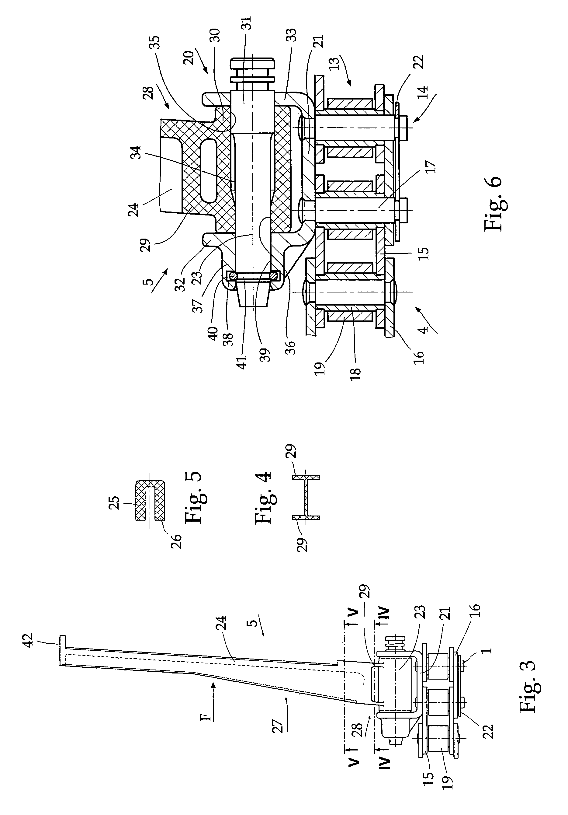
The invention aims to make it easy to disassemble or replace parts without causing strain on the traction mechanism or taking too much time. This is achieved by designing pushers with a predetermined breaking zone located away from the mounting point. This prevents any damage to other parts of the conveying element when the pusher breaks.

Problems solved by technology

Both during the gathering of the printed products and during the transfer from the gathering machine to the perfect binder, it happens that printed products collide on the conveying tract and are displaced relative to the conveying direction, so that a backup then develops, which can cause the pusher, which is made of plastic, to break.
Furthermore, in addition to the breaking of the pusher finger, the hinge, the holder, and / or chain links of the traction mechanism are damaged and thus must be replaced.
This results in increased repair expense, especially since there are only “a few” places along the conveying line at which there is enough room to be able to repair the damage.
Accessibility to the chain with tools is limited in most cases, and it is no simple matter for the repairman to do his job properly in tight spaces with screws, nuts, bolts, and lock rings.

Method used


Image

  • Device for conveying book blocks on a conveying line of a machine for producing books, magazines, or the like
  • Device for conveying book blocks on a conveying line of a machine for producing books, magazines, or the like
  • Device for conveying book blocks on a conveying line of a machine for producing books, magazines, or the like

Examples


Embodiment Construction

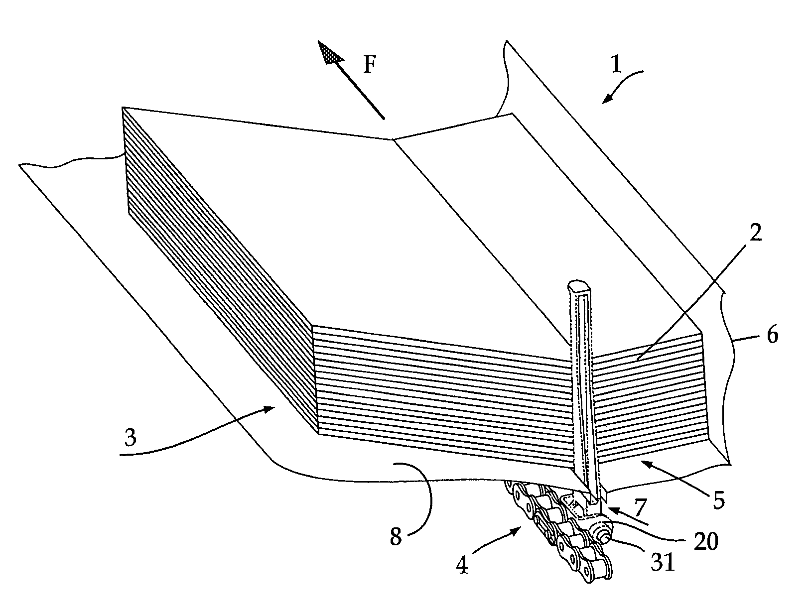
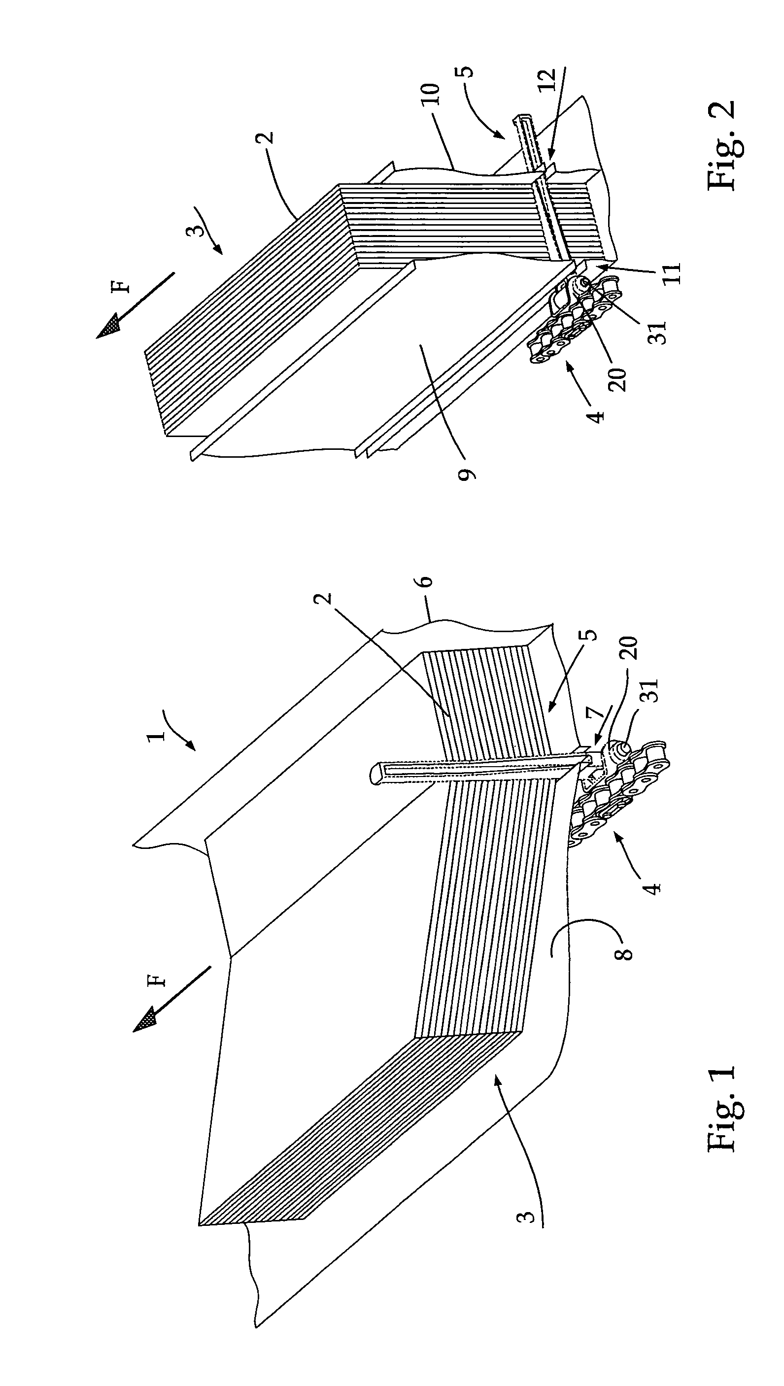
[0018]FIG. 1 shows a section of a conveying channel 1 of a gathering machine, in which a loose book block 3 consisting of gathered signatures 2 is located. The book block 3 is conveyed at its back end (relative to the conveying direction F) by a pusher 5 mounted on a driven conveying chain that is used as the traction mechanism 4. The conveying channel 1 has a guide wall 6, which the signatures 2 strike fold first as they are fed individually from the opposite side by signature feeders 43. The pushers 5, which are mounted at regular intervals on the revolving conveying chain, run in a slot 7 in the base 8 of the channel and serve to convey the forming book block 3.

[0019]At the end of the gathering line, the conveying channel 1 turns about 90° in the conveying direction, so that the book block 3 is standing on the folded spines of the signatures 2 and is further conveyed by the pusher 5, which has also turned 90°. FIG. 2 illustrates the book block standing on its spine, which is form...


PUM

PropertyMeasurementUnit
distanceaaaaaaaaaa
diameteraaaaaaaaaa
tensionaaaaaaaaaa

Abstract

A conveyance device for the pressing of glued spines of a book block for books, in which the book blocks, with their spines directed downward, pass through a pressing section that reduces the spine swell. The book blocks, gripped between working pieces of revolving traction elements, pass through the pressing section, which acts on the sidepieces of the book spine.

Description

BACKGROUND OF THE INVENTION[0001]1. Field of the Invention[0002]The present invention relates to a device for conveying book blocks on a conveying line of a machine for producing books, magazines, or the like, along which conveying line a revolving conveying element is installed, which conveys the book blocks and is designed with finger-like pushers that are mounted on a traction mechanism and project into a conveying channel transversely to the conveying direction.[0003]2. Description of the Related Art[0004]Devices of the aforementioned type are known, for example, in installations for producing perfect-bound book blocks or books and in back-gluing machines, especially for thread-stitched book blocks.[0005]In gathering machines, to form loose book blocks by feeders arranged along a conveying line, a conveying channel is loaded with printed products, and the book blocks, which are formed from stacked printed products are fed, standing on the spine of the book block, to a perfect bi...

Claims


Application Information

Patent Timeline
Patent Type & Authority Patents(United States)
IPC IPC(8): B65H39/00B42B5/00B42C19/08B65G19/26B65G43/06B65H5/00B65H5/16B65H31/28
CPCB42C19/08B65G19/265B65H31/28B65H5/16B65H2301/4352
Inventor STOLZ, THOMAS
Owner MULLER MARTINI HLDG
Learn More