Flat-panel display using tapered waveguide

a technology of tapered waveguides and flat panels, applied in television systems, identification means, instruments, etc., can solve problems such as prone to distortion of projected images, and achieve the effect of reducing blurring and improving contrast ratio

Inactive Publication Date: 2008-08-12
MICROSOFT TECH LICENSING LLC
View PDF9 Cites 193 Cited by
  • Summary
  • Abstract
  • Description
  • Claims
  • Application Information

AI Technical Summary

Benefits of technology

[0019]FIG. 6 shows how a set of louvers and fine scattering sites can be used to reduce blurring and improve contrast ratio; and

Problems solved by technology

These displays are cheap and robust because the screens need no thin-film transistors and can be made of plastic, but the projected image can be prone to distortion.

Method used


Image

  • Flat-panel display using tapered waveguide
  • Flat-panel display using tapered waveguide
  • Flat-panel display using tapered waveguide

Examples


Embodiment Construction

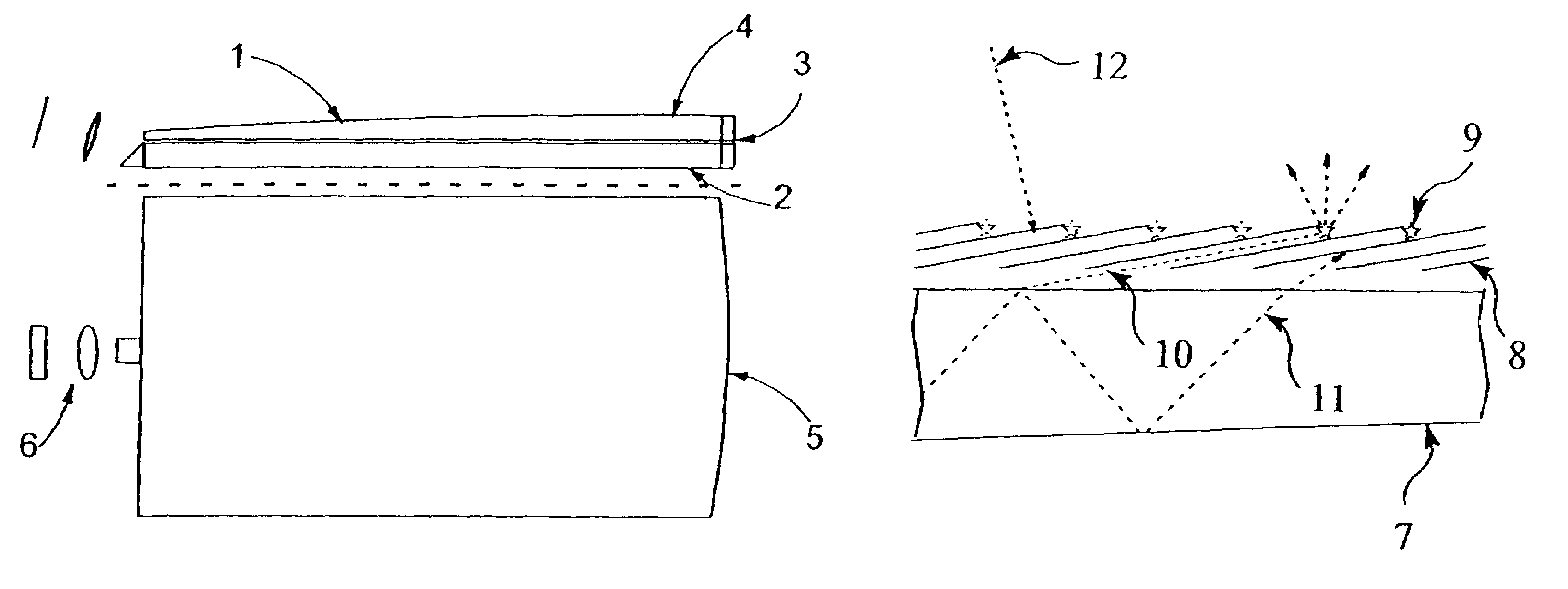
[0023]FIG. 7 shows the general layout contemplated by the invention. A projector 6 (or camera if the apparatus is operated backwards, or just a point light source for producing area illumination) emits (or receives) light forming an image made of an array of pixels into an edge 71 of a rectangular slab waveguide 2 where it propagates by reflection alternately off the main faces. This slab will usually have flat parallel faces, though this is not necessary. As the light propagates it spreads laterally, in the plane of the slab and perpendicular to the direction of propagation, by the far end 72 reaching the entire width of the slab. Thus the image is as it were magnified in the width direction. There it is collimated by a cylindrical lens 73 to enter the blunt end 74 of a slab waveguide 1 of equal width but tapering in height in the direction away from the projector. Here it is also internally reflected, but at ever increasing (steeper) angles 75-77 until at the critical angle given ...


PUM

PropertyMeasurementUnit
refractive indexaaaaaaaaaa
thickaaaaaaaaaa
thickaaaaaaaaaa

Abstract

A video display for two or three dimensions has a flat liquid-crystal screen which ejects light from the plane at a selectable line. One or, in the case of a 3-D display, several video projectors project a linear image into the plane from an edge. A complete image is written on the screen by addressing the line with appropriate images as it is scanned down the screen. To screen a three-dimensional image, the video projectors, each projecting an image as seen at a slightly different angle, combine to constitute a three-dimensional display which produces a three-dimensional image that is one line high.

Description

CROSS-REFERENCE TO RELATED APPLICATIONS[0001]Not applicableSTATEMENT REGARDING FEDERALLY SPONSORED RESEARCH OR DEVELOPMENT[0002]Not applicableREFERENCE TO A “MICROFICHE APPENDIX”[0003]Not applicableBACKGROUND OF THE INVENTION[0004]1. Field of the Invention[0005]This invention is concerned with a way of eliminating distortion in a tapered-waveguide display of the kind in which light enters the blunt end of a tapered slab waveguide.[0006]2. General Background of the Invention[0007]Such a tapered-waveguide display comprises a video projector, a flat slab waveguide, known as an “input” or “expansion” waveguide, for spreading light from the projector in the width direction, and a tapered sheet of transparent material acting as a leaking waveguide, light exiting from its face at a point determined by the angle at which it entered. The taper starts at the same thickness as the expansion waveguide and decreases usually to zero. Light entering the taper at some angle up to the critical angle...

Claims


Application Information

Patent Timeline
Patent Type & Authority Patents(United States)
IPC IPC(8): F21V7/04F21V8/00G02F1/13357G03B21/00G09F9/00G09F13/00G09F13/18H04N5/74
CPCG02B6/0046H04N9/3141Y10S385/901G02F1/025
Inventor TRAVIS, ADRIAN ROBERT LEIGH
Owner MICROSOFT TECH LICENSING LLC
Why Eureka
Try Eureka