Arctic platform

a technology of arctic platform and arctic water, which is applied in the direction of drilling pipes, drilling equipment, insulation, etc., can solve the problems of difficult transportation of drilling equipment to the drilling site, inability to support trucks and other heavy equipment, and general shallow water for traditional equipment flotation

Active Publication Date: 2008-08-12
ANADARKO PETROLEUM CORPORATION CORP
View PDF36 Cites 15 Cited by
  • Summary
  • Abstract
  • Description
  • Claims
  • Application Information

AI Technical Summary

Problems solved by technology

Some potential drilling and production sites are further constrained by special circumstances that make transportation of drilling equipment to the drilling site especially difficult.
In the case of swamps, muskegs, and tidal flats, the ground is generally too soft to support trucks and other heavy equipment, and the water is generally too shallow for traditional equipment to be floated in.
Moreover, certain production sites are disposed in environmentally sensitive regions, where surface access by conventional transport vehicles can damage the terrain or affect wildlife breeding areas and migration paths.
Such environmental problems are particularly acute in, for example, arctic tundra and permafrost regions.
In these areas, road construction is frequently prohibited or limited to only temporary seasonal access.
However, drilling in such regions presents substantial engineering and environmental challenges.
However, in the Alaskan North Slope, the tundra is closed to all traffic from May 15 to July 1 due to nesting birds.
From the foregoing, it is clear there are several drawbacks associated with current arctic drilling and production technology.
Also, the ice roads can become contaminated with lubricant oil and grease, antifreeze, and rubber products.
In addition to the environmental impact, the economic costs associated with arctic drilling can be prohibitively high.
At the beginning of each drilling season, the ice roads and pads must all be rebuilt, and equipment must again be transported to and removed from the site, all at substantial financial and environmental cost.
Such remediation efforts can be very costly and difficult to accomplish.

Method used


Image

  • Arctic platform
  • Arctic platform
  • Arctic platform

Examples


Embodiment Construction

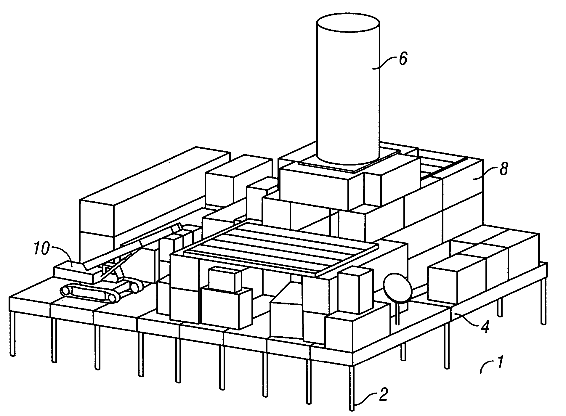
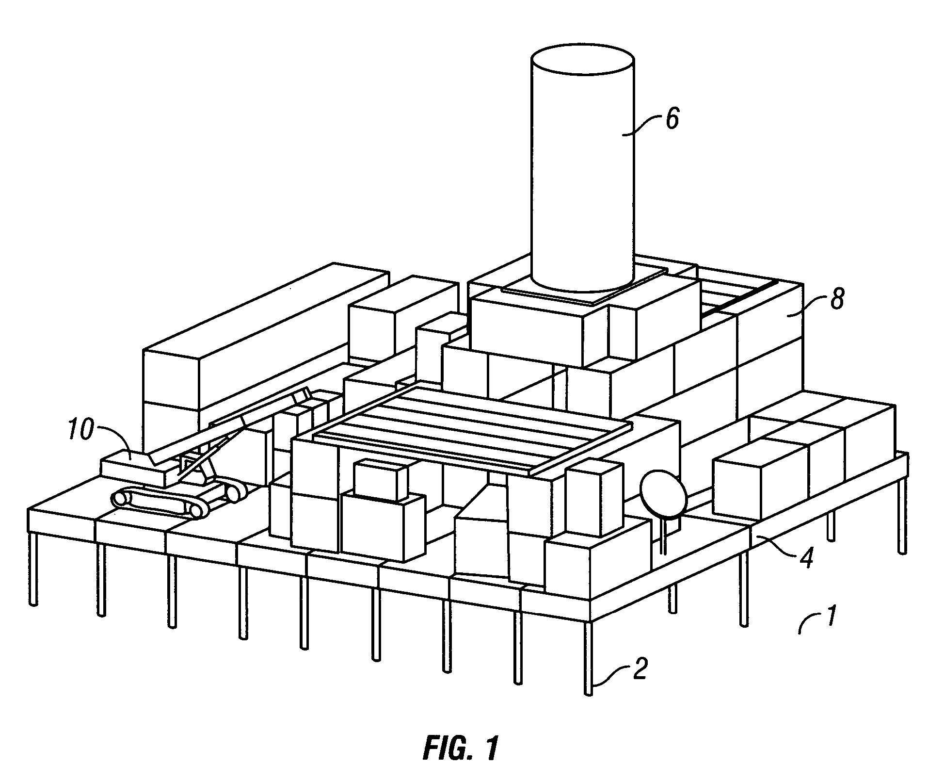
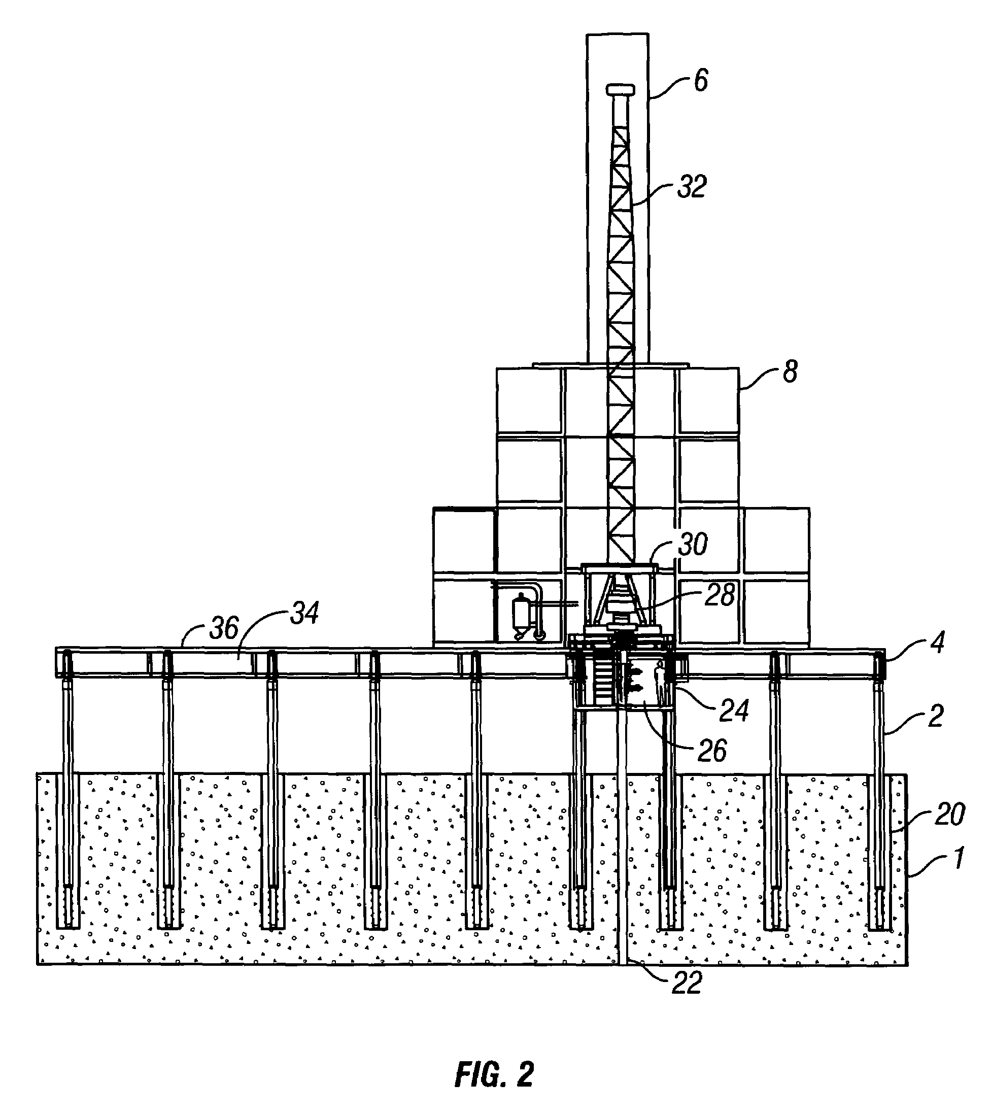
[0082]Referring now to a specific, though non-limiting, embodiment of the invention shown in FIG. 1, a tundra region 1 is shown in which a number of support posts 2 are disposed in a number of post holes drilled into the tundra. The support posts 2 support a substantially level drilling or production platform 4 comprised of numerous interconnected modular platform sections. In certain embodiments, a cylindrical (or other shape) winterizer 6 encloses and winterizes a drilling rig (not shown), and a number of easily transportable modular platform sections 8 are installed around the drilling rig. In some embodiments, for example, where drilling is carried out at very cold temperatures (e.g., in arctic tundra regions), the rig area is heated during drilling operations. In a particular embodiment in which the platform is used for hydrate production, the rig area is only heated to an intermediate temperature of about +10 degrees F., so that recovered hydrates will not thaw and can be pres...


PUM


Abstract

The instant disclosure relates to a system and method of constructing drilling and production platforms that are particularly useful in remote, inaccessible and / or environmentally sensitive operating environments. According to one aspect of the invention, an arctic drilling platform is provided wherein various methods and means of interlocking neighboring platform modules are provided. Methods and means for sealing the intersections formed between a plurality of interlocked platform modules are also disclosed. According to further aspects of the invention, improved platform floor plans are provided, and various wellhead cellar layouts and sealing means are also described. Methods and means of enhancing the usefulness of modular storage platforms are disclosed, and a number of support post installation and removal techniques are also provided. Also taught are a variety of methods of adjusting the height and level of an assembled drilling platform, and methods and means of adding extension members useful for extending the length of a support post are also described.

Description

RELATED APPLICATION DATA[0001]The instant application, filed under 35 U.S.C. § 111(a), claims the benefit under 35 U.S.C. § 120 as a continuation of U.S. Non-Provisional patent application Ser. No. 10,820,597, filed under 35 U.S.C. § 111(a) on Apr. 8, 2004 now abandoned, which claimed the benefit under 35 U.S.C. § 119(e) of U.S. Provisional Application No. 60,461,602, filed under 35 U.S.C.§ 111(b) on Apr. 8, 2003.FIELD OF THE INVENTION[0002]The present invention relates generally to the field of oil and gas drilling and production. In a specific, non-limiting embodiment, the invention comprises a system and method of drilling oil and gas wells in arctic, inaccessible or environmentally sensitive locations without significantly disturbing an associated ground surface.DESCRIPTION OF THE PRIOR ART[0003]The drilling and maintenance of land oil and gas wells requires a designated area on which to dispose a drilling rig and associated support equipment. Drilling locations are accessed by ...

Claims


Application Information

Patent Timeline
Patent Type & Authority Patents(United States)
IPC IPC(8): E02D27/00E02B17/00E02B17/02E02D3/115E02D27/35E21BE21B36/00E21B41/00
CPCE02D27/35E02D27/12E02D3/115E02B2017/0052
Inventor BAUGH, BENTON F.WATSON, CRAIGMILLHEIM, KEITH KKADASTER, ALI G.
Owner ANADARKO PETROLEUM CORPORATION CORP
Why Eureka
Try Eureka