Method of controlling a fluid flow

a fluid flow and fluid technology, applied in the direction of particle separator tube details, instruments, chemistry apparatus and processes, etc., can solve the problems of large and unacceptable ozone concentrations, large diameter of existing ozone monitors, and relatively high cost, so as to prevent sagging, increase diameter, and maintain the effect of wire straightness

Inactive Publication Date: 2008-08-12
TESSERA INC
View PDF291 Cites 18 Cited by
  • Summary
  • Abstract
  • Description
  • Claims
  • Application Information

AI Technical Summary

Benefits of technology

[0046]As noted, due to thermal expansion the corona wire elongates along its length (and, to some extent, increases in diameter) as it is heated. Depending on the wire's length and temperature increase the wire may sufficiently elongates so as to sag. Sagging may disadvantageously occur to the extent that the corona wire comes closer to or into contact with other wires or parts of the EFA. Needless to say, the resultant short-circuits, arcing, and similar outcomes are undesirable. To prevent sagging and in order to maintain wire straightness, each wire may be supplied with an individual spring or other biasing means for maintaining tension on the wire. Unfortunately, this solution to wire sagging is relatively expensive to implement. In order to maintain the wires straight using a cost effective design, the frame that supports the corona wires may consist of separate parts with different spring or biasing mechanisms and capabilities. Such a corona frame generally has opposing bar-like wire supports to which wires are attached or otherwise mounted / supported and two flat spring-like connecting pieces attached to the bars, outwardly biasing the bars. When the wires are initially attached to the bars the spring-like pieces are slightly bent. When the wires are finally falsely secured to the bars the spring-like pieces are released. These spring-like pieces keep the wires straight even as temperature changes cause their length to vary. Spring action also prevents the corona wires from sagging when the wires are heated to high temperature during a cleaning or electrode decontamination cycle.
[0047]For some applications the entire corona frame and corona electrode assembly can be made disposable. This may be desirable because, after some period of time the corona wire deteriorates to the extent that it should be replaced. Corona frame life span may be doubled if the corona frame is made two-sided. That is, the corona wire is applied to both sides of the corona frame. In this case, the portion of the corona wire located on the side closer to the opposing electrodes, e.g., accelerating electrodes, is active. It is this active portion of the corona wire that generates the corona discharge and emits ions toward the accelerating electrodes. The corona wires that are located on the opposite side (or “focus”) of the corona frame (FIG. 11) are inactive, i.e. they do not generate the corona discharge since they are located too distant from the opposite accelerating electrodes. These inactive (opposite) wires are not contaminated or deteriorated since they are not in an area of the corona discharge. After some period of time the operating or active wire ages to the extent that it can no longer operate efficiently and cannot or should not be used. At this point, the corona frame may be flipped 180° so that the opposite side wires are positioned near the accelerating electrodes and thereby become active. This arrangement doubles the average life span of the corona frame while incurring only marginal additional expense.
[0049]Another important requirement is that all or substantially all of the ozonated air should pass through high temperature area. That is there should be no leakage or bypass for the air other than through the hot area. Thus, a feature of the current invention includes a hot area that is designed to embrace substantially all airflow exhausted through an outlet of an EFA. This way all air passing through the hot area will be heated so as to attain a desirable high temperature such that substantially all ozone is destroyed. Still another important feature is that the hot area should have sufficient temperature to destroy ozone within its entire volume. If some portions of the hot area are not maintained at a sufficiently high temperature then air that passes through this “cold” portion will still include some non-destroyed ozone. Thus, an important feature of the hot area design is that it provides what may be characterized as a “hot curtain” having a sufficient path length to keep air within this curtain for a time period sufficient to destroy ozone and reduce a level of any residual ozone to a required safe level.

Problems solved by technology

Prior attempts to increase air velocity have lead to increased ozone generation resulting in unsafe ozone levels not suitable for human habitat.
This problem is most evident and of concern when an EFA operates near or at maximum capacity, i.e., with some maximum voltage applied and power consumed.
Such problem arises when a more robust fluid flow is necessary or desirable (e.g., higher fluid flow rates).
In such conditions even a small amount of ozone generation may lead to large and unacceptable ozone concentrations after some relatively short period of operating time.
Therefore a need exists not only to minimize or eliminate zone generation but for the efficient control of ozone content in the air: Unfortunately, existing ozone monitors are large and relatively expensive.
These compact sensors, however, require a substantial airflow through the sensor body an airflow on the order of greater than 2 liters per minute.
Such fans are expensive and generate an unpleasant background noise that negates one of the benefits of an electrostatic air cleaner-silent operation.

Method used


Image

  • Method of controlling a fluid flow
  • Method of controlling a fluid flow
  • Method of controlling a fluid flow

Examples


Embodiment Construction

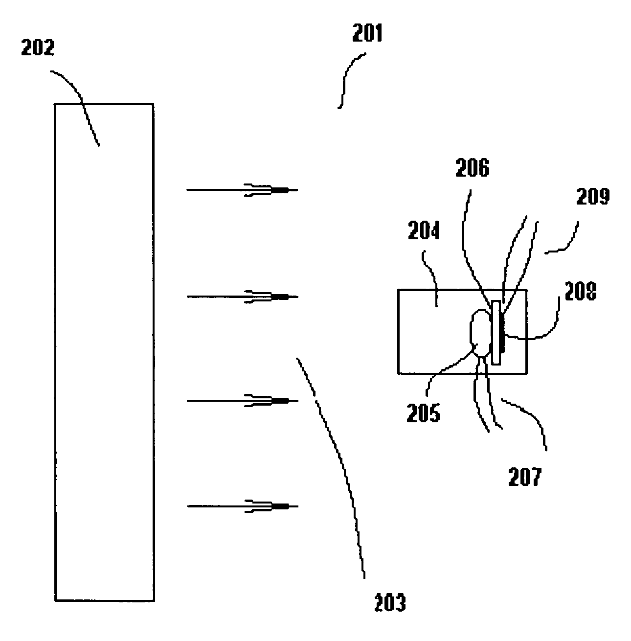
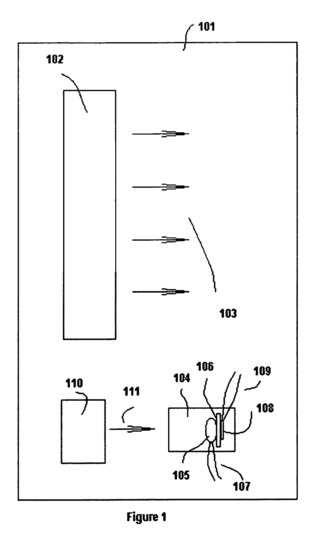
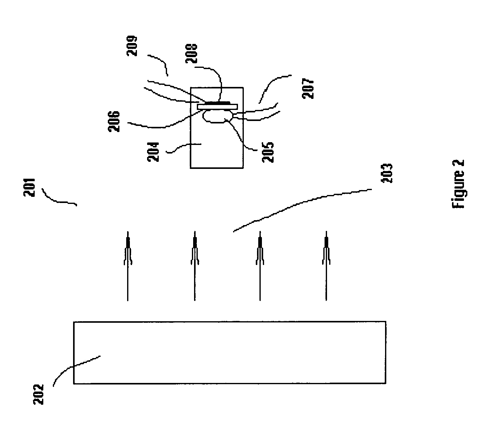
[0071]FIG. 1 depicts a conventional electrostatic fluid accelerator (EFA) 101 EFA 101 includes array 102 operable to accelerate air in direction 103 by electrostatic force. Complementary to the electrode array 102 ozone detector 104 is included as part of EFA 101. Ozone detector 104 contains a base portion in the form of substrate 106 with ozone sensitive sensor 105 mounted to one side of substrate 106. Heating filament 108 is located on the other side of the substrate 106. Ozone sensor 105 is connected to control circuitry via wires 107. Heating filament 108 is connected to an appropriate power supply (not shown) via wires 109.

[0072]Mechanical fan 110 is provided to blow air through ozone detector 104. A typical commercially available ozone detector made by a company such as City Technology (Citytech) requires an airflow of at least 2 liters per minute through sensor 105. Fan 110 should capable to deliver that amount of air. Unfortunately, suitable mechanical fans are noisy and do ...


PUM


Abstract

An electrostatic fluid accelerator includes an electrode array including an array of corona discharge electrodes and an array of accelerating electrodes. A detector is configured to sense a constituent component of the fluid as present in an output from the electrode array. A control circuit supplies power to the electrode array, the control circuit being responsive to an output from the detector for operating the electrode array responsive a level of the constituent component.

Description

CROSS-REFERENCE TO RELATED APPLICATIONS[0001]The instant application claims the benefit of U.S. Provisional Application No. 60 / 649,560, filed Feb. 4, 2005, pursuant to 35 U.S.C. 119(e) and is related to and incorporates herein by reference in their entirety applicant's previously filed U.S. Patent Applications as follows:BACKGROUND OF THE INVENTION[0002]1. Field of Invention[0003]The invention relates to a device for accelerating, thereby imparting velocity and momentum to a fluid, and particularly to the use of corona discharge technology to generate ions and electrical fields for the movement and control of fluids including gases such as air, liquids, etc.[0004]2. Description of the Related Art[0005]A number of patents (see, e.g., U.S. Pat. No. 4,210,847 by Shannon, et al. and U.S. Pat. No. 4,231,766 by Spurgin) describe ion generation using an electrode (termed a “corona electrode”), for accelerating charged particles (i.e., “ions”) toward another electrode (termed an “accelerati...

Claims


Application Information

Patent Timeline
Patent Type & Authority Patents(United States)
IPC IPC(8): B03C3/00H01J49/04
CPCH01J49/04C01B13/11
Inventor KRICHTAFOVITCH, IGOR A.OHARAH, JACOB L.BIBIKOV, VOLODYMYR A.MARTIN, CHRISTOPHER A.GOROBETS, VLADIMIR L.ZIOMKOWSKI, MACIEJ R.TAM, TERENCE TAK-SHING
Owner TESSERA INC
Why Eureka
Try Eureka