Wave power plant

a power plant and wave technology, applied in the field of plants, can solve the problems of not fully utilizing the power of the wave, complicated system, and inability to utilize the energy of the wave's components that move under the wave, and achieve the effect of maximum energy production and little for

Inactive Publication Date: 2008-08-12
Y T ENTERPRISES +1
View PDF20 Cites 21 Cited by
  • Summary
  • Abstract
  • Description
  • Claims
  • Application Information

AI Technical Summary

Benefits of technology

[0074](ii) The present invention has at least two paddles. The Fr Patent 501795 has one paddle. The advantage of the present invention from this reason is the same as explained in 2(i) above as regards towards U.S. Pat. No. 5,084,630.[0075]9. JP patent 006750 converters can only exploit linear movement, and does not make it possible to exploit the dynamic energy of the sea waves. The hydraulic cylinders 2 and 2a, are pistons connected to a float 1 and this enables the linear movement of the pistons within the piston casing. As a result the pistons within the casing, by virtue of the rising level of water, require very little force to rice. However, since energy is always a product of force multiplied by distance, the resultant energy is very small as a consequence of the small amount of force exerted.
[0075]9. JP patent 006750 converters can only exploit linear movement, and does not make it possible to exploit the dynamic energy of the sea waves. The hydraulic cylinders 2 and 2a, are pistons connected to a float 1 and this enables the linear movement of the pistons within the piston casing. As a result the pistons within the casing, by virtue of the rising level of water, require very little force to rice. However, since energy is always a product of force multiplied by distance, the resultant energy is very small as a consequence of the small amount of force exerted.
[0076]The present invention, however, is based on a different principle, i.e., the exploitation of the dynamic energy of sea waves, which give rise to pivotal movement of the paddles rather than their elevation. The pivotal movement is subsequently converted into linear movement of the bi-directional piston by means of a crankshaft mechanism 32, 40. The piston rises within the casing with relatively great force and while the energy produced is a product of force multiplied by distance, the resultant energy is higher as a consequence of the high amount of force exerted. Thus the energy produced according to this system is greater then JP patent 006750.
[0077]10. U.S. Pat. No. 4,490,621 described a system for generating energy with two hydraulic motors, one hydraulic motor 121a, for low waves and one hydraulic motor 121b for high waves with very complicated system. When the oil pressure PLa>PLb then first hydraulic motor 121a works and when the oil pressure PLa<PLb, the second hydraulic motor works. The present invention works with all kinds of oil pressure with the same hydraulic motor. If for example, the present invention works with a system of three hydraulic motors, the U.S. Pat. No. 4,490,621 requires 6 hydraulic motors: three for law waves plus three for high waves, which is very expensive and with very complicated system. The present invention is more economical and much simpler than U.S. Pat. No. 4,490,621.
[0078]11. U.S. Pat. No. 1,960,622 generate energy does not establish optimum distance of the paddle heights, to make plan maximum energy production, since the rod 20 and the plate 25 move upwards or downwards synchronously, automatically, but not supervised as described in the present invention, with the movement of the sea level at tide time.
[0079]The paddles' system according to the present invention stays in the optimum fixed position even when the sea water continues to move upwards and downwards with the tide to create the plant maximum energy production, while in the U.S. Pat. No. 1,960,622, the rod 20 and the plate 25, move upwards or downwards all the time with the sea water at the tide time.

Problems solved by technology

Hence, the wave's power is not fully utilized.
Due to this provision the whole system is complicated, as it requires additional control means for coordination of the paddle disposition with the variation in sea level.
Furthermore, as the disposition of the paddle is continuously changed and the paddle is not submerged deeply enough to maximally utilize available energy, it is not possible to utilize the energy of those wave's components that move under the wave.
In this way the accumulator can't be filled and work properly.
The PCT / IL99 / 00258 patent requests can't make progress from the accumulator to the generator, because the accumulator does not work.
When the plant is large each of the paddles have a big weight, which bring to a high momentum with high energy loss.
Because such a great rod length is required, the profile of the rod proposed in GB 384603A or in Patent JP 57081168 is extremely thick and large, so that it should not bend under the force of the waves, and quite impractical.
Because of the weight of the rod proposed in GB 384603A or in Patent JP 57081168, and the slow wave speed prevailing under said conditions, it is not possible to attain the minimum speed of 500 rpm required to rotate the flywheel of the oil pump (linked to the accumulator that drives an oil engine, which in turn drives a generator and produces the electric energy).
Where higher waves are concerned, the entire plant proposed by GB 384603 A or by Patent JP 57081168 become dysfunctional and cannot be used.
The above converter can only exploit linear monement, and does not make it possible to exploit the dynamic energy of the sea waves.
However, since energy is always a product of force multiplied by distance, the resultant energy is very small as a consequence of the small amount of force exerted.
In order to attain such high speeds, when the wave movement is relatively low, it is necessary to provide additional transmission by means of a few pairs of cog-wheels, thus creating losses in the system.
Moreover, if we introduce a number of pairs of cog-wheels, then the total efficiency of the system is reduced, and the energy produced is thus far lower.
The cost of the system too, is increased through the provision of may pairs of additional cogwheels.
However, since energy is always a product of force multiplied by distance, the resultant energy is very small as a consequence of the small amount of force exerted.

Method used


Image

  • Wave power plant
  • Wave power plant
  • Wave power plant

Examples


Embodiment Construction

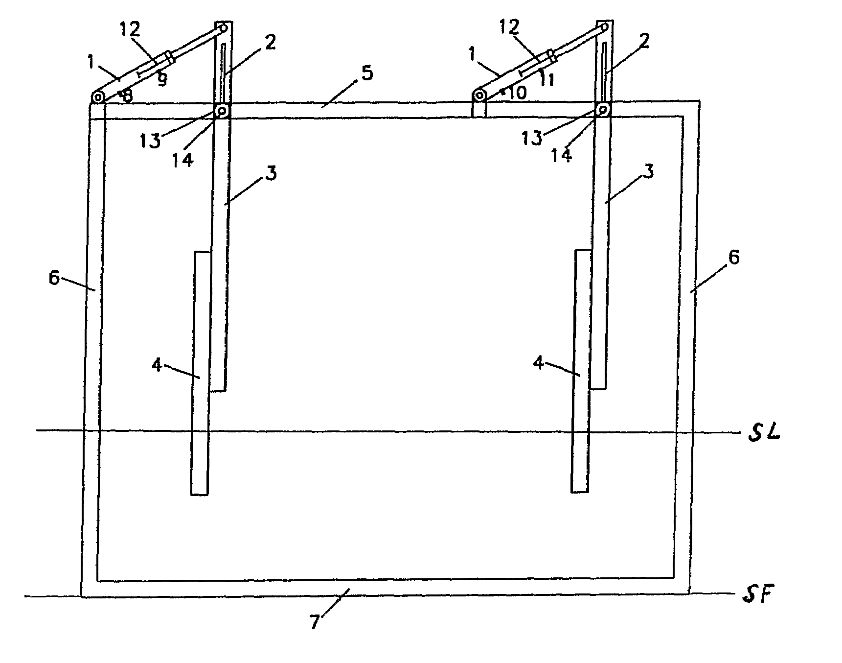
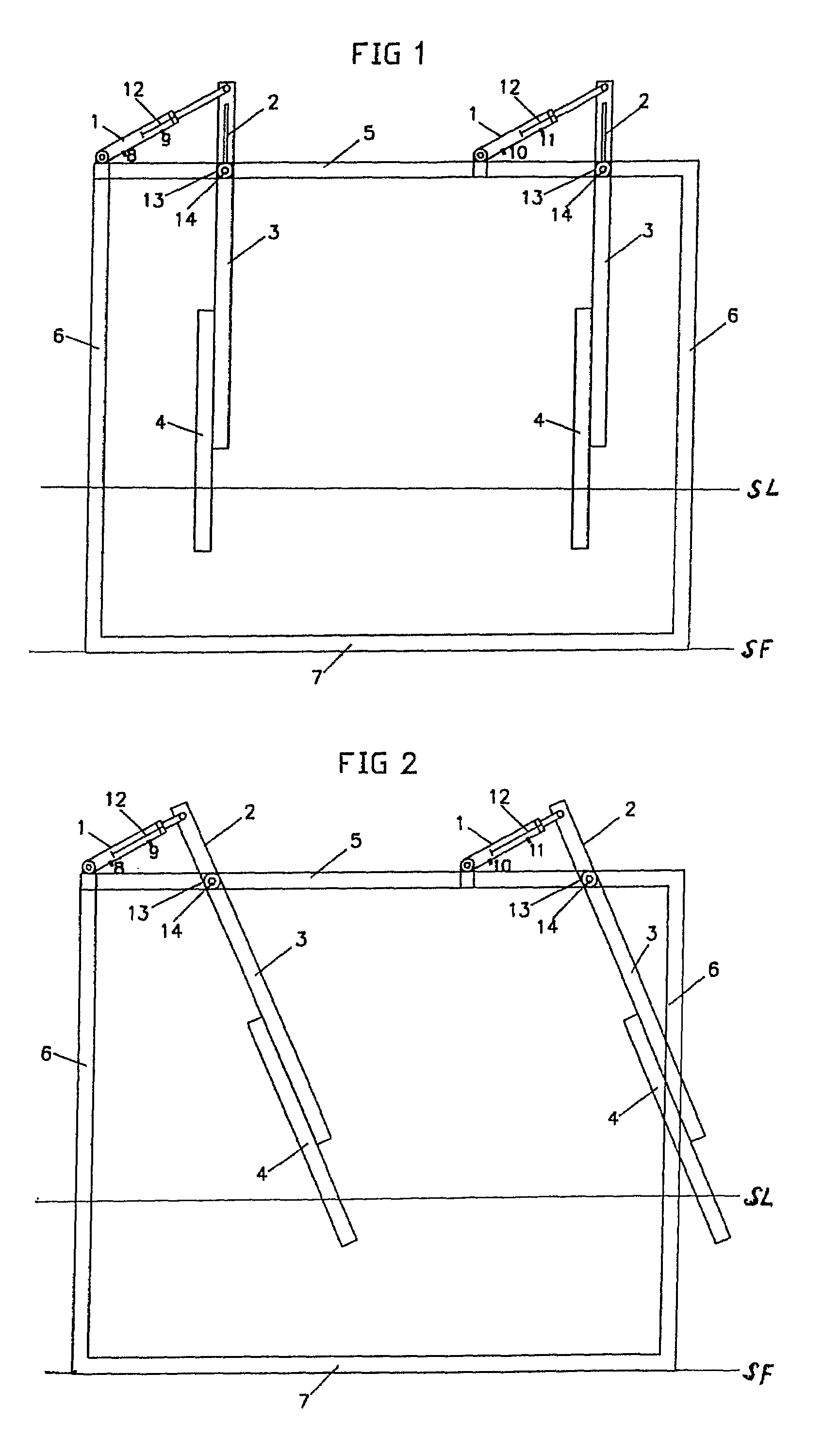
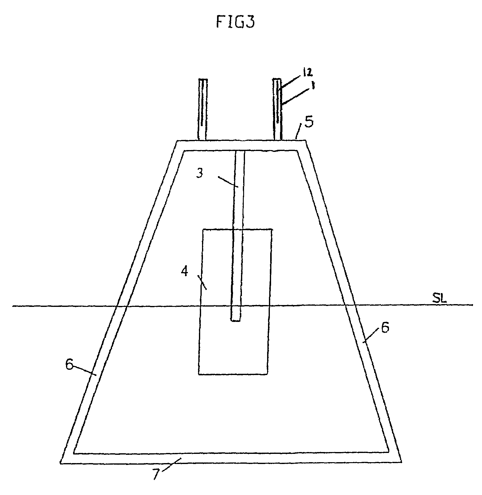
[0087]With reference to FIG. 1, the system in accordance with the present invention comprises a support structure 7 consisting of legs 6 carrying an upper frame 5. The legs are anchored in the sea floor SF. SL is the sea level.

[0088]On the upper frame there are mounted at least two paddle units, which will be described in more detail below, Each paddle unit comprises a paddle rod 3 connected to a housing 13. Within the housing there is mounted an axle 14, which is rigidly secured to the upper frame.

[0089]Each paddle unit comprises a paddle rod 3 rigidly connected to the housing 13. The housing is mounted around an axle 14, secured to the upper frame 14. A rotational movement of the housing with respect to the axle is accomplished by virtue of a pivotal movement of the paddle rod 3 with the plate 4, driven by a wave.

[0090]The lower extremity of the paddle rod 3 is terminated by a paddle plate 4, which encounters the wave and is driven thereby. The height of the legs 6 and also the di...


PUM


Abstract

Wave power plant consisting of frame carrying at least two paddles unit, capable of moving successively in series, when driven by progressive waves and returning by the gravitation power and the backward wave's force. The plant has an appropriate means with at least one crankshaft mechanism for transferring the successive motion of paddle units in two ways into electric energy. Each of the paddles units have a rod, to be submerged into the sea and which is secured on the frame with possibility for pivoting with respect thereof, the lower extremity of the rod is terminated by a paddle plate and the paddles units are arranged around the frame in series. The energy consumed successfully by each paddle unit is equal to the energy of the paddle's movement forward from the forward wave's force plus the energy of the paddle's movement backward from the backward wave's force and the paddle's gravity. The plant's energy is consumed, in at least one hydraulic engine, which rotate generators.

Description

FIELD OF THE INVENTION[0001]This invention relates to a plant, which uses the energy of sea waves plus the energy of gravitation and converts these energies into electric energy. The plant according to this invention can produce high power production.BACKGROUND OF THE INVENTION[0002]There are different solutions for the production of energy from sea waves, for example, solutions based on wave height, wave movement, etc. The present invention utilizes both the wave length and the wave width by the forward wave motion, the backward wave motion and the force of gravity in the most efficient way, something that other proposed solutions do not.[0003]The following are examples of the innovation inherent in the present invention as compared with the patents enumerated below, both from the point of view of the operating principle and structure, and from the point of view of energy considerations—allowing greater energy to be attained and produced.[0004]1. (i) U.S. Pat. No. 5,084,630 utilize...

Claims


Application Information

Patent Timeline
Patent Type & Authority Patents(United States)
IPC IPC(8): F03B13/12F03B13/18
CPCF03B13/182Y02E10/38Y02E10/30
Inventor TAL-OR, YANIV
Owner Y T ENTERPRISES
Why Eureka
Try Eureka