Electromagnetic interference shield for I/O ports

a technology of electromagnetic interference shield and i/o port, which is applied in the direction of electrical apparatus casing/cabinet/drawer, instrumentation, aperture leaage reduction, etc., can solve the problems of inability to accept the amount of electromagnetic signals that radiate from the computer, adversely affecting other electronic equipment positioned nearby, and increasing manufacturing costs

Active Publication Date: 2008-08-12
HEWLETT-PACKARD ENTERPRISE DEV LP
View PDF36 Cites 21 Cited by
  • Summary
  • Abstract
  • Description
  • Claims
  • Application Information

AI Technical Summary

Problems solved by technology

Electronic equipment, such as computers in a rack-based server system, radiate electromagnetic signals, which can cause electromagnetic interference (EMI) adversely affecting other electronic equipment positioned nearby.
These gaps may allow an unacceptable amount of electromagnetic signals to radiate from the computer.
This can undesirably increase manufacturing costs, in addition to adding delays to the design timeline for new products.

Method used


Image

  • Electromagnetic interference shield for I/O ports
  • Electromagnetic interference shield for I/O ports
  • Electromagnetic interference shield for I/O ports

Examples


Embodiment Construction

[0018]In the following description, reference is made to the accompanying drawings which illustrate several embodiments of the present invention. It is understood that other embodiments may be utilized and mechanical, compositional, structural, electrical, and operational changes may be made without departing from the spirit and scope of the present disclosure. The following detailed description is not to be taken in a limiting sense, and the scope of the embodiments of the present invention is defined only by the claims of the issued patent.

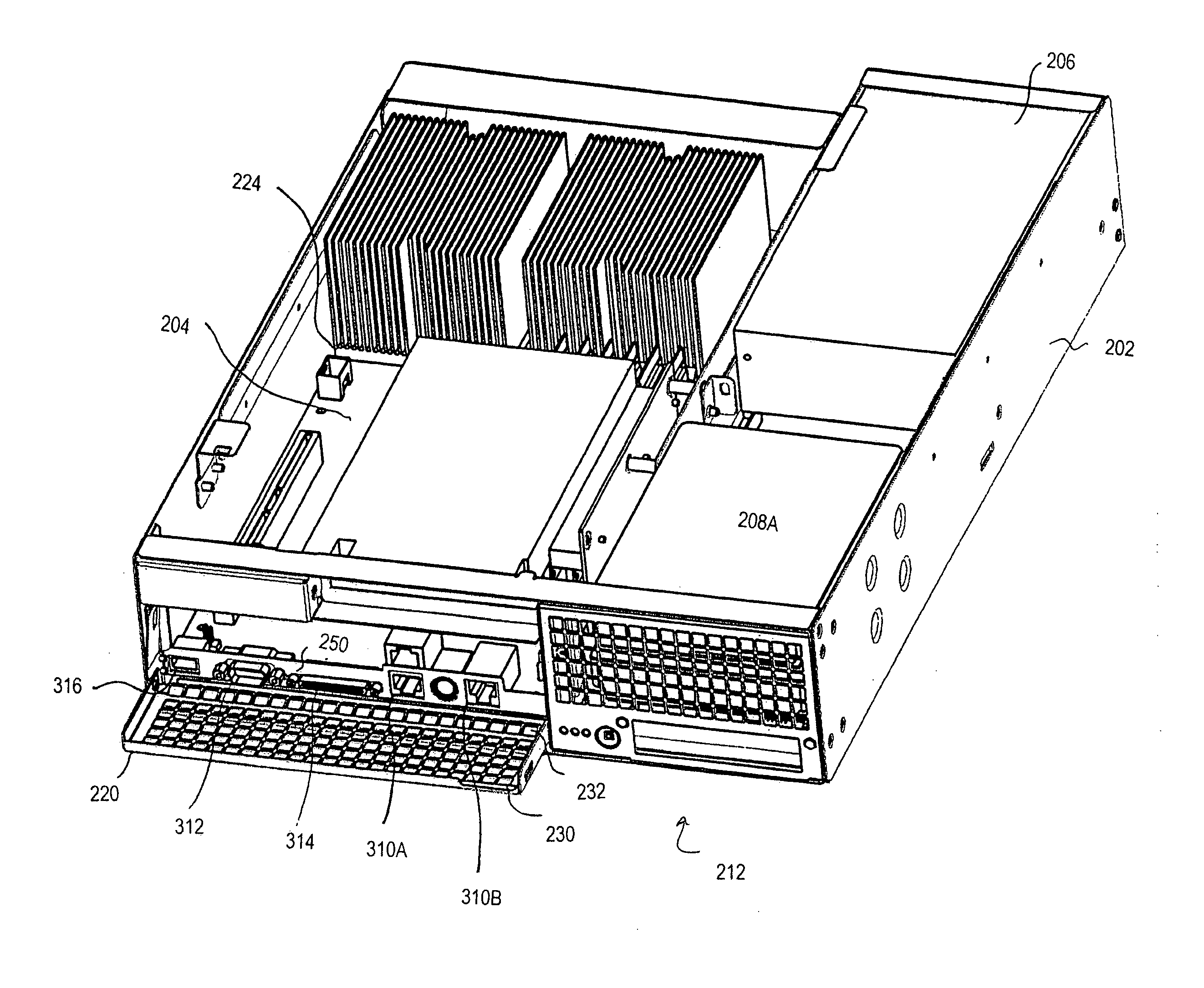
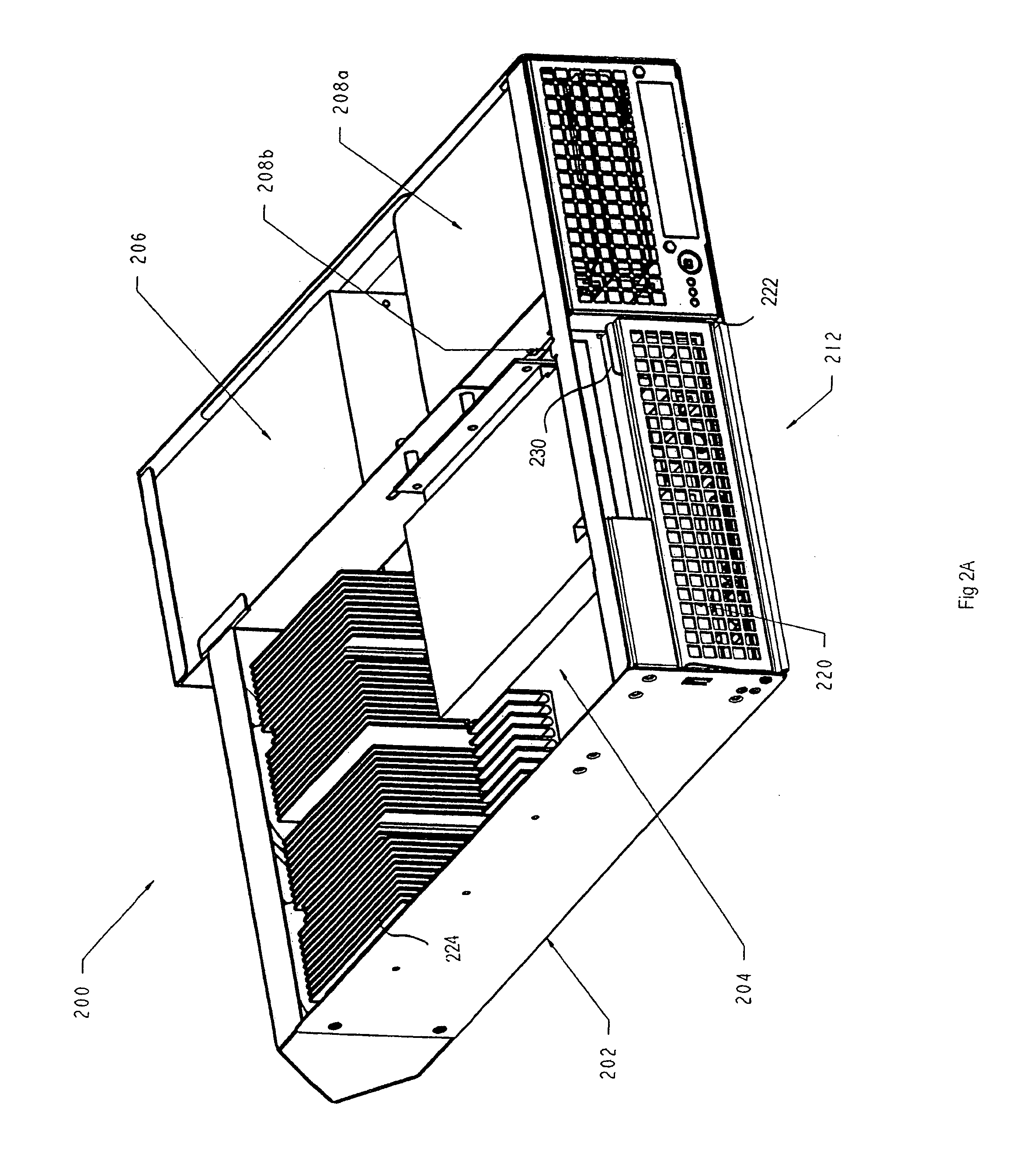
[0019]FIGS. 2A and 2B show perspective views of a computer 200 with the top cover 210 removed, in accordance with embodiments of the present invention. The computer 200 may comprise a computer chassis 202 containing a motherboard 204 and other components, such as one or more power supplies 206, hard drives 208a-208b, processors 224, and expansion cards. An exemplary computer 200 is described in greater detail in the following U.S. patent applica...


PUM


Abstract

A computer system is provided, including: a computer chassis configured to retain a motherboard having a plurality of I / O (input / output) connectors mounted thereon; and an electrically conductive door movable from an open position to a closed position, wherein when said door is in the open position, the I / O connectors are exposed, and when said door is in the closed position, the I / O connectors are covered. A method of operating a computer including a motherboard having a plurality of I / O (input / output) connectors mounted thereon is provided. The method includes operating the computer to generate electromagnetic signals, and blocking the electromagnetic signals with an electrically conductive door movable from an open position to a closed position, wherein when said door is in the open position, the I / O connectors are exposed, and when said door is in the closed position, the I / O connectors are covered.

Description

RELATED APPLICATION[0001]The present application claims the benefit of U.S. Provisional Patent Application Nos. 60 / 569,020, filed on May 7, 2004 and entitled “ELECTROMAGNETIC INTERFERENCE SHIELD FOR I / O PORTS”; 60 / 568,969, filed May 7, 2004 and entitled “INTERFACE ASSEMBLY”; 60 / 569,025, filed May 7, 2004, entitled “RACK MOUNTED COMPUTER SYSTEM”; and 60 / 569,019, filed May 7, 2004 and entitled “DIRECTIONAL FAN ASSEMBLY”, all of which are hereby incorporated by reference as if fully set forth herein.BACKGROUND[0002]1. Field[0003]This is related generally to electronic equipment, such as computer systems including a plurality of input / output connectors associated therewith. Certain aspects relate to methods and systems for selectively shielding or blocking electromagnetic signals from a computer system.[0004]2. Description of Related Art[0005]Electronic equipment, such as computers in a rack-based server system, radiate electromagnetic signals, which can cause electromagnetic interferen...

Claims


Application Information

Patent Timeline
Patent Type & Authority Patents(United States)
IPC IPC(8): G06F1/16G06F1/18H05K5/00H05K9/00
CPCH05K9/0018G06F1/182
Inventor COGLITORE, GIOVANNIRANDALL, JACK E.CASEBOLT, MATTHEW P.
Owner HEWLETT-PACKARD ENTERPRISE DEV LP
Why Eureka
Try Eureka