
Image forming apparatus

a technology of forming apparatus and forming device, which is applied in the direction of electrographic process apparatus, instruments, optics, etc., can solve the problems of non-uniformity and inability to meet the demand for miniaturization of developing device, and achieve the effect of minimizing the effective developing width of the developing devi

Inactive Publication Date: 2008-08-12
FUJIFILM BUSINESS INNOVATION CORP
View PDF5 Cites 2 Cited by
  • Summary
  • Abstract
  • Description
  • Claims
  • Application Information

AI Technical Summary

Benefits of technology

Enables satisfactory image formation on both standard and long-width sheets while minimizing the developing device's width, addressing the challenge of miniaturization and mechanical tolerance issues.

Problems solved by technology

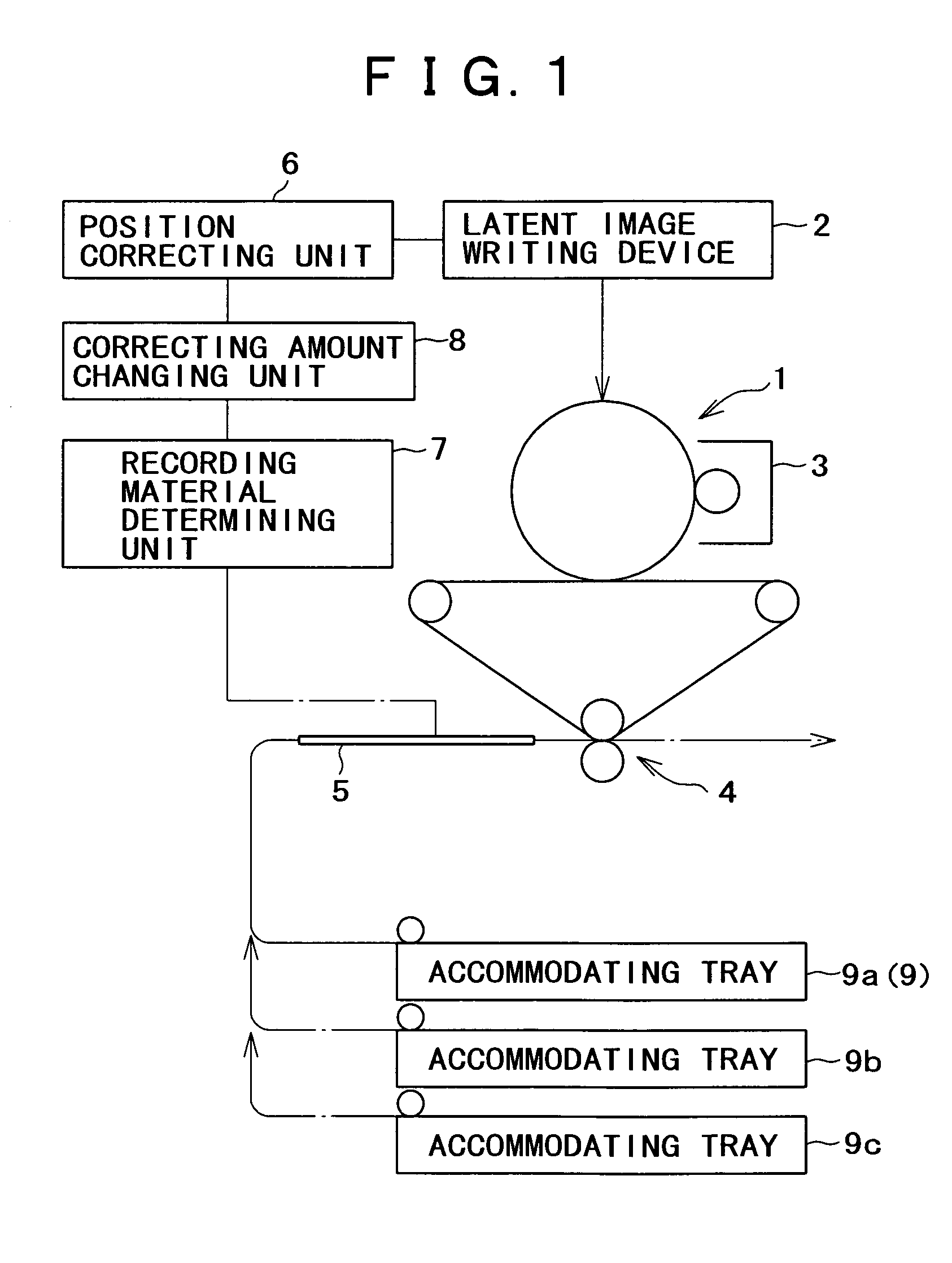
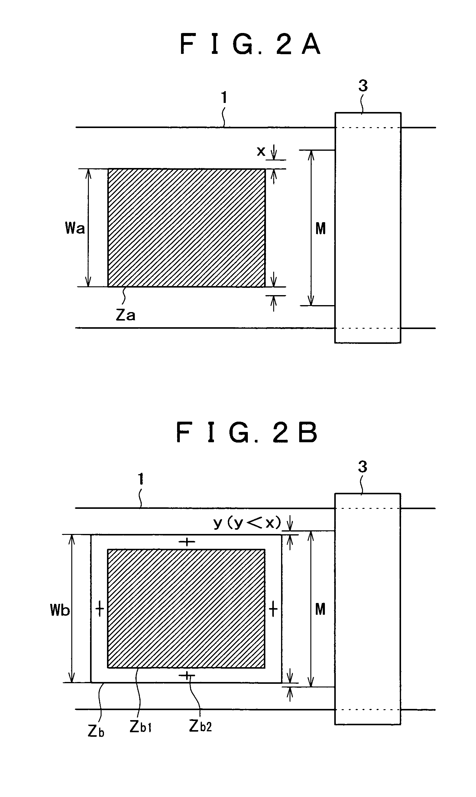
In this case, non-uniformness exists in each accommodating tray due to a mechanical tolerance, so that the position for accommodating the sheet varies for every tray in the widthwise direction (corresponding to the direction perpendicular to the advancing direction of the sheet).
Therefore, the width of the developing device should be more enlarged than necessary, thereby entailing a technical problem of not meeting the demand for miniaturization of the developing device.

Method used


Image

  • Image forming apparatus
  • Image forming apparatus
  • Image forming apparatus

Examples


first embodiment

[0053]FIG. 3 is an explanatory view showing an overall construction of an image forming apparatus according to the first embodiment to which the present invention is applied.

[0054]In this figure, the image forming apparatus has an imaging module 10 disposed in a device body 21 and a sheet transport system 30 disposed below the imaging module 10.

[0055]The imaging module 20 applies an electrophotographic system of a so-called intermediate transfer type. It has a photoreceptor drum 11 and an intermediate transfer belt 17 arranged opposite to the photoreceptor drum 11 and circularly moves. Disposed around the photoreceptor drum 11 are a charger 12 for charging the photoreceptor drum 11, an exposure device 13 for writing an electrostatic latent image onto the photoreceptor drum 11, a rotary-type developing device 14 for making the electrostatic latent image formed on the photoreceptor drum 11 visible with toner of each color component, a primary transfer device 15 for primarily transferr...


PUM


Abstract

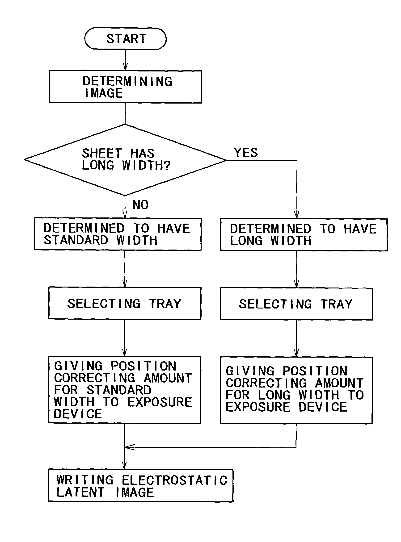
An image forming apparatus has a latent image writing device that writes an electrostatic latent image on an image bearing member, a developing device that develops a toner image based on the electrostatic latent image, a transferring device that transfers the toner image onto a recording material, a position correcting unit that corrects a position of the electrostatic latent image written by the latent image writing device, a recording material determining unit that determines whether or not the recording material has a long width, and a corrected amount changing unit that, when the recording material determining unit determines that the recording material has a long width, changes an amount of correcting the position of the electrostatic latent image to a value different from a set value for a recording material having a standard width.

Description

BACKGROUND OF THE INVENTION[0001]1. Field of the Invention[0002]The present invention relates to an image forming apparatus such as a copying machine, printer and the like, and more particularly to an improvement in an image forming apparatus in which image forming on a recording material having a long width is possible.[0003]2. Description of the Prior Art[0004]Explaining this type of the conventional image forming apparatus by taking, for example, an electrophotographic system as an example, there has been the one provided with a latent image writing device for writing an electrostatic latent image to a photoreceptor drum as an image-bearing member, a developing device for making this electrostatic latent image visible and a transferring device for transferring this developed image onto a sheet as a recording material.[0005]In this type of image forming apparatus, an adopted latent image writing device is provided with a charger for charging the photoreceptor drum and an exposure ...

Claims


Application Information

Patent Timeline
Patent Type & Authority Patents(United States)
IPC IPC(8): G03G15/043G03G15/04G03G15/28G03G15/30G03G21/14G03G15/00G03G15/16
CPCG03G15/5095G03G2215/00759
Inventor KANEKO, SHINTAROMURATA, SHIGEMIHATTORI, RYUJI
Owner FUJIFILM BUSINESS INNOVATION CORP
Learn More