Radio communication system

a radio communication and wireless communication technology, applied in the field of wireless communication systems, can solve problems such as inability to secure periods, and achieve the effect of improving the entire data transmission efficiency of the system and ensuring transmission quality

Inactive Publication Date: 2008-08-12
SONY CORP
View PDF12 Cites 23 Cited by
  • Summary
  • Abstract
  • Description
  • Claims
  • Application Information

AI Technical Summary

Benefits of technology

[0016]This invention has been made in view of the above points and intends to provide a wireless communication system capable of keeping a fixed beacon interval, securing transmission quality and performing intermittence reception without fail.
[0020]The main beacon and the sub beacon are transmitted with the beacon time period information included therein, and the wireless terminal device divides and transmits transmission data so that transmission of the transmission data is finished before transmission of the main beacon is started, and thereby overlap of transmission timings of the beacon and the transmission data can be prevented and the beacon interval can be fixed with sure, which can secure transmission quality and perform intermittence reception without fail, and further improve entire data transmission efficiency of the system.

Problems solved by technology

This means that the start timing of a next non-conflict period is delayed, and thus the QoS during the non-conflict period can not be secured, which is a problem.
Therefore, if the beacon interval lengthens, a timing of the intermittent reception becomes different from a timing of transmission of a beacon and thus the fourth terminal station operating in the intermittence reception mode can not receive the beacon, which is a problem.

Method used


Image

  • Radio communication system
  • Radio communication system
  • Radio communication system

Examples


Embodiment Construction

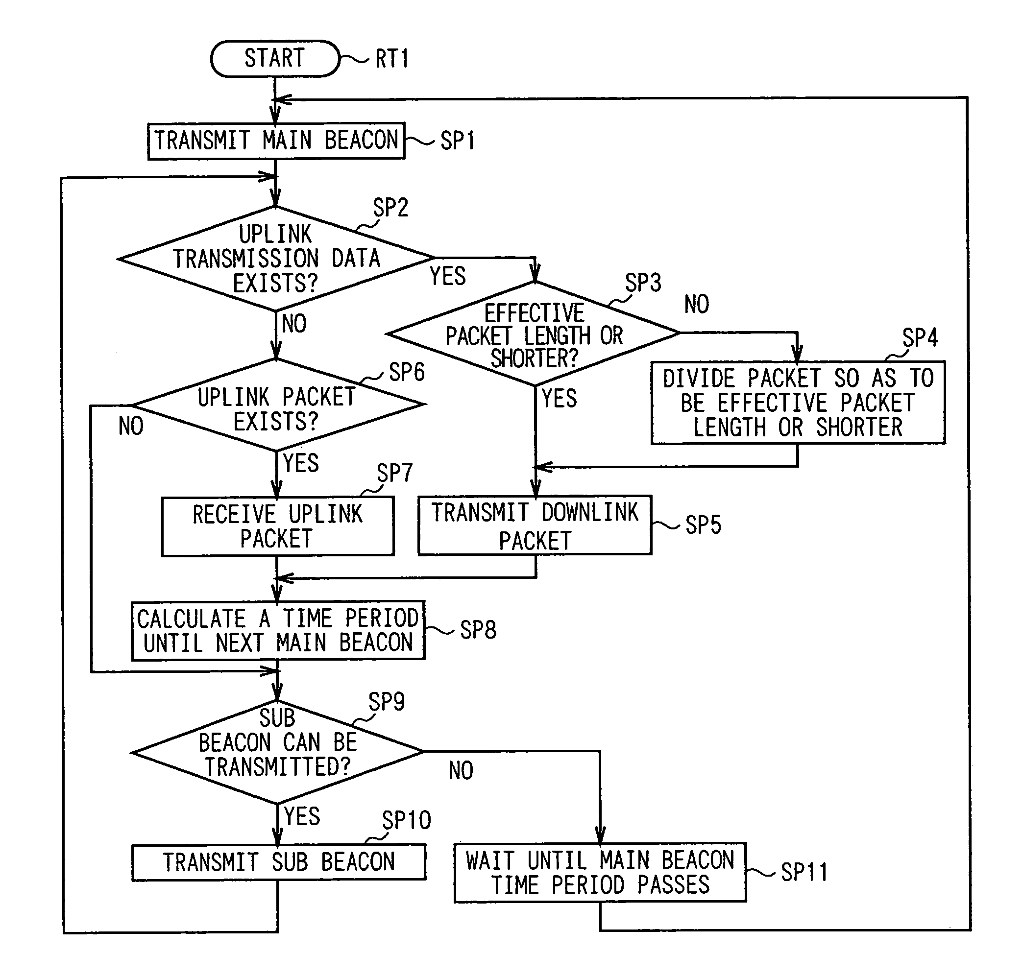
[0031]Hereinafter, one embodiment of this invention will be described in detail with reference to drawings:

(1) Entire Construction of Wireless LAN System

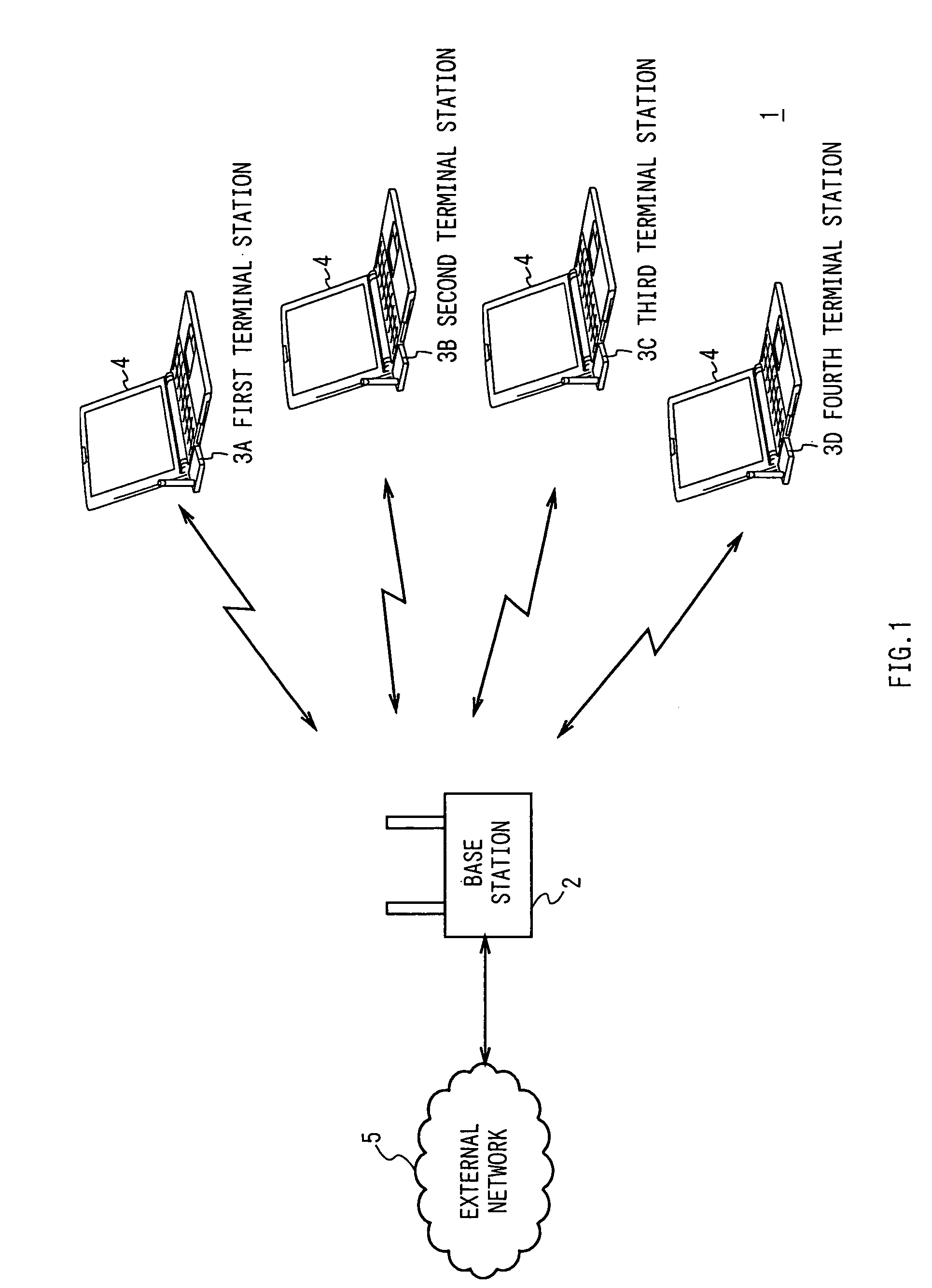
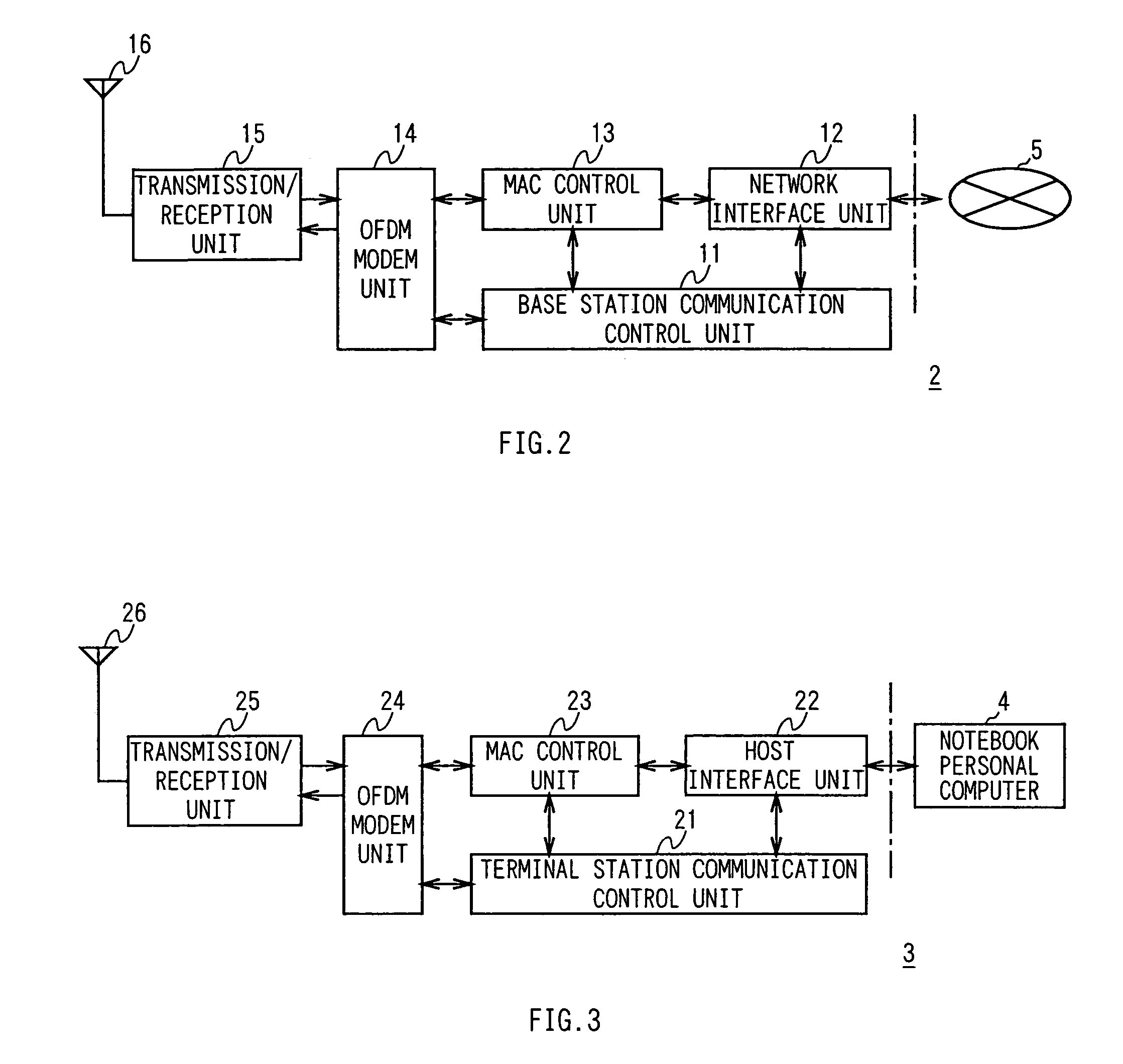
[0032]Referring to FIG. 1, reference numeral 1 generally shows a wireless LAN system as a wireless communication system according to this invention, and this system is composed of a base station 2 as a wireless communication management device and first to fourth terminal stations 3 (3A to 3D). The base station 2 and the terminal stations 3A to 3D perform wireless communication with each other with the CSMA / CA scheme, for example, in 5 GHz band.

[0033]In actual, the terminal stations 3A to 3D as wireless terminal devices are wireless LAN cards of a PC card type, and are being inserted into the PC card slots of corresponding notebook personal computers (hereinafter, referred to as notebook personal computer) 4. On the other hand, the base station 2 is connected to an external network 5 such as the Internet and an intranet.

[0034]In the ...


PUM


Abstract

To realize a wireless communication system capable of keeping a beacon interval fixed, keeping transmission quality, and performing intermittence reception without fail. A wireless communication management device includes and transmits beacon time period information in a main beacon and a sub beacon. Then, a wireless terminal device divides transmission data based on the beacon time period information so that the transmission of the transmission data is finished before the transmission of a main beacon is started. Thereby, overlap of transmission timings of the beacon and the transmission data can be prevented and the beacon interval can be made fixed. This can keep transmission quality, makes the wireless terminal device to perform intermittence reception without fail, and improve the entire data transmission efficiency of the system.

Description

TECHNICAL FIELD[0001]This invention relates to a wireless communication system, and more particularly, is suitably applied to a wireless LAN (Local Area Network) system, for example.BACKGROUND ART[0002]Recently, wireless LAN systems, in which the IEEE (Institute of Electrical and Electronics Engineers) 802.11b and IEEE802.11a are typical systems, are widely used. In the wireless LAN systems of the IEEE802.11 type, an autonomous decentralized system using a CSMS / CA (Carrier Sense Multiple Access / Collision Aviodance) scheme as an access scheme is used (for example, refer to a patent reference 1).[0003]That is, FIG. 9 shows a protocol stack of the lower two layers in an OSI (Open System Interconnection) model of an IEEE802.11-type wireless LAN system, which is composed of a data link layer 901 and a physical layer 902.[0004]The data link layer 901 is divided into a LLC (Logical Link Control) sublayer 903 and an MAC (Media Access Control) sublayer 904. In the IEEE wireless LAN system, a...

Claims


Application Information

Patent Timeline
Patent Type & Authority Patents(United States)
IPC IPC(8): H04B15/00H04J11/00H04L12/28
CPCH04W48/12H04W56/00H04W84/12
Inventor FUKUDA, KUNIO
Owner SONY CORP
Why Eureka
Try Eureka