Split winch band shaft fast rotating device

a technology of rotating device and split winch, which is applied in the mechanical field, can solve the problems of increasing manufacturing difficulty and manufacturing process, high cost, and out of use of whole winch, and achieves the effects of reducing use cost, increasing operational flexibility, and increasing manufacturing difficulty and manufacturing processes

Active Publication Date: 2008-08-19
ZHEJIANG TOPSUN LOGISTIC CONTROL CO LTD
View PDF11 Cites 23 Cited by
  • Summary
  • Abstract
  • Description
  • Claims
  • Application Information

AI Technical Summary

Benefits of technology

[0007]An object of the present invention is to provide a split band shaft fast rotating device used with a winch, which can be mounted and removed at any moment, so that the use cost is decreased while the operational flexibility is increased. In this way, the above-mentioned problems associated with the prior art can be addressed, in which the band shaft rotating device is integrated with the winch, with the result of increased manufacturing difficulty and manufacturing processes as well as high cost.
[0008]Another object of the present invention is to provide a split winch band shaft fast rotating device which facilitates ordinary maintenance. Once the rotating device is damaged beyond repair, it can directly be replaced, in order to make the winch keep on working. In this way, the technical problems associated with the prior art can be addressed, in which it is hard to maintain and once damaged, the whole winch will be out of use, with the result of high cost.
[0009]Yet another object of the present invention is to provide a split winch band shaft fast rotating device which makes the winch band shaft rotate fast. Wherein, the crowbar doesn't need to be pulled out during operation so as to make the operation convenient, labor saving, safe and reliable and increase the bundling speed of the winch. In this way, the technical problems associated with the prior art can be addressed, in which the operational process is complicated and inefficient, and takes time and labor, furthermore, the crowbar needs to be pulled out and inserted on and on during use.

Problems solved by technology

In this way, the above-mentioned problems associated with the prior art can be addressed, in which the band shaft rotating device is integrated with the winch, with the result of increased manufacturing difficulty and manufacturing processes as well as high cost.
In this way, the technical problems associated with the prior art can be addressed, in which it is hard to maintain and once damaged, the whole winch will be out of use, with the result of high cost.

Method used


Image

  • Split winch band shaft fast rotating device
  • Split winch band shaft fast rotating device
  • Split winch band shaft fast rotating device

Examples


first embodiment

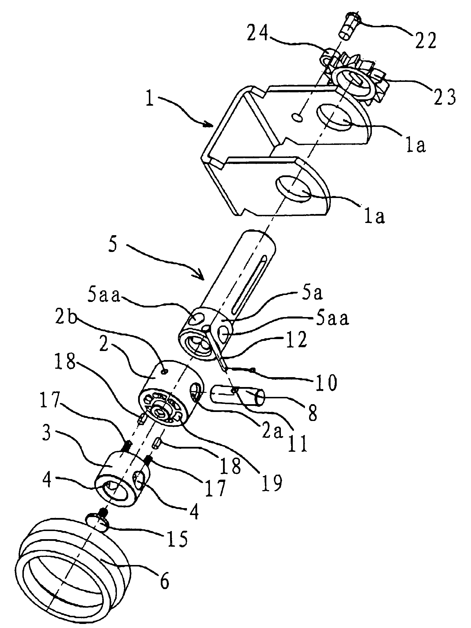
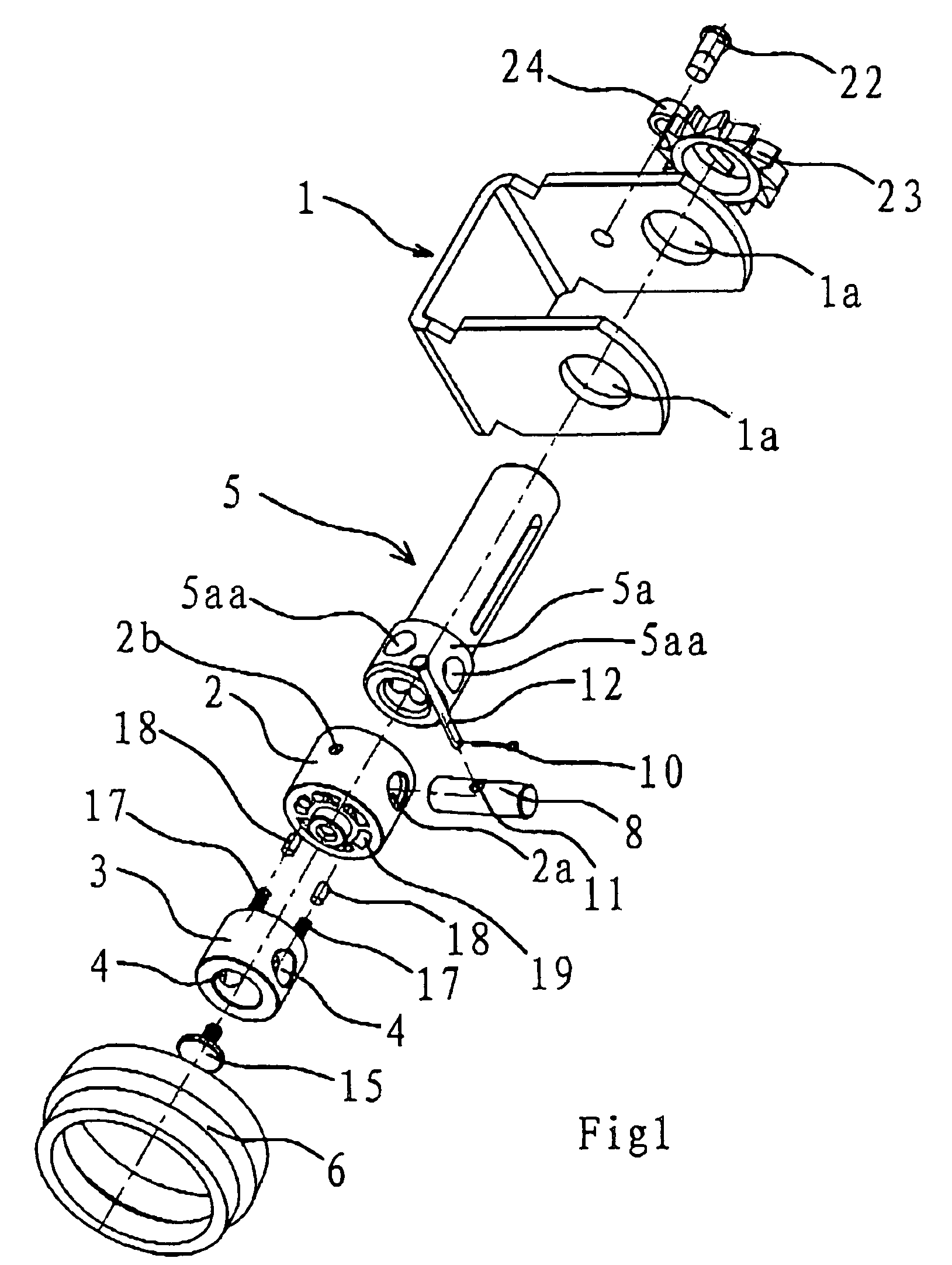
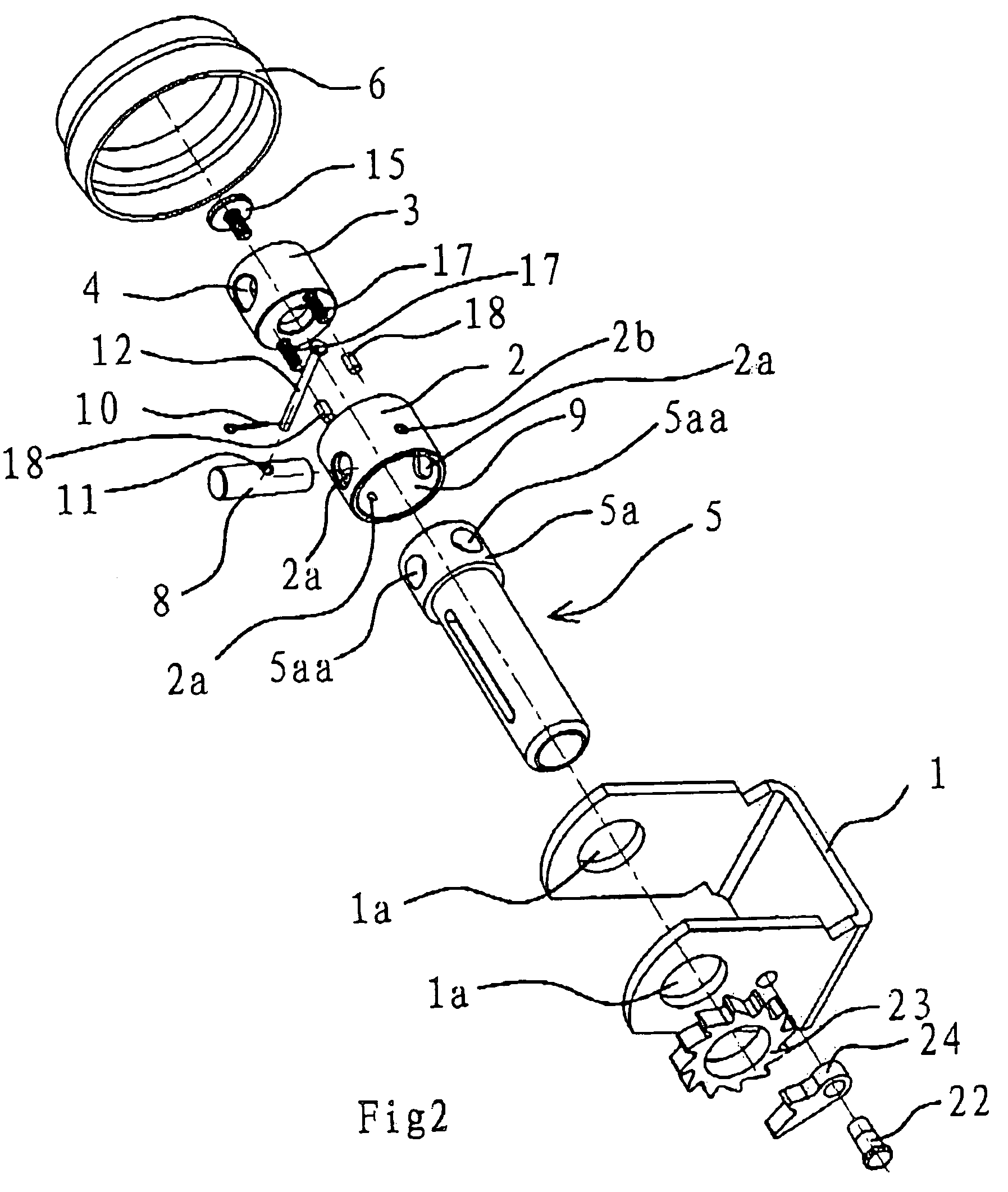
[0049]With reference to FIGS. 1-4, the split winch band shaft fast rotating device of the present invention is disposed at the band shaft extension end 5a at one side of the winch mount 1. The device includes a band shaft joint 2 and a rotator 3 with two crowbar holes 4 for receiving a crowbar oppositely arranged thereon. A unidirectional ratchet wheel 23 fixedly connected to the band shaft 5 is set at the other side of the winch mount 1. One end of the band shaft 5 extends out of one side of the winch 1 through the band shaft holes 1a of the winch mount 1. The ratchet wheel 23 is fixedly connected to this extension end. A ratchet 24 is set at one side of the unidirectional ratchet wheel 23 for seizing the ratchet wheel as shown in FIG. 5, so that the band shaft 5 could only rotate in one way during winding. In this embodiment, the ratchet axle 22 is fixedly connected to one side of the winch mount 1 and the ratchet 24 is sticked to the ratchet axle 22, so that the ratchet 24 will n...

second embodiment

[0059]Another embodiment of the fast rotating device of the present invention is shown in FIGS. 14, 15 and 16. In this embodiment, one end of the band shaft joint 2 is a post 7, which is inserted into the band shaft extension end 5a. Four pin holes 5aa are uniformly distributed on the band shaft extension end 5a. Four axle pins 8 pass through the corresponding pin holes 5aa on the band shaft extension end 5a and are fixedly connected to the threaded holes 25 on the post 7. The axle pins 8 and post 7 fixedly connect the band shaft extension end 5a to the band shaft joint 2 by thread fitting.

[0060]As shown in FIG. 14, a protruded riveting block 13 is disposed at one end of the band shaft joint 2 with a stopper 14 riveted thereto. The rotator 3 is blocked by the outer edges of the stopper 14 after it is covered on the band shaft joint 2, so that the rotator 3 will not be detached from the band shaft joint 2.

[0061]When in use, the post 7 of the band shaft joint 2 is inserted into the ba...


PUM

PropertyMeasurementUnit
operational flexibilityaaaaaaaaaa
bundling speedaaaaaaaaaa
connecting strengthaaaaaaaaaa

Abstract

A split winch band shaft fast rotating device is provided herein. The device is disposed at the band shaft extension end at one side of the winch mount, and includes a band shaft joint and a rotator. At least one crowbar hole is set on the rotator. The rotator is coupled to one side of the band shaft joint with a unidirectional linkage mechanism set at the contact surface thereof. The band shaft extension end has at least one pin hole. The band shaft joint could be inserted into or covered on the band shaft extension end with a detachable connection mechanism arranged therebetween which could make the joint fixedly connected to the extension end by inserting one or more axle pins into the pin holes. The split winch band shaft fast rotating device is low in cost, convenient in maintenance, flexible in operation, and could improve the bundling speed of the winch.

Description

BACKGROUND OF THE INVENTION[0001]1. Field of Invention[0002]The present invention relates to mechanical field, and more particularly to a bundling tool for automobiles.[0003]2. Related Art[0004]Goods usually need to be bundled during transportation, in order to prevent from being dropped off when the automobile runs and colliding with each other with the result of loss or damage. Though it is a usual way to bundle goods directly with ropes, it takes time and labor, and is difficult to bundle goods tightly, thereby inducing safety problems.[0005]The winch is popular with drivers as an advanced bundling tool, as it is convenient and safe to bundle goods with the winch. Currently, the winch widely used is provided with a mount and a band shaft, wherein the band shaft is installed at the mount and can rotate. The bundling bands of the bundler wrap around the band shaft. In this way, the bundling bands are tightened by rotating the band shaft, so that the goods can be bundled tightly. Th...

Claims


Application Information

Patent Timeline
Patent Type & Authority Patents(United States)
IPC IPC(8): B66F3/00
CPCB60P7/083Y10T24/2121
Inventor RUAN, BOQIN
Owner ZHEJIANG TOPSUN LOGISTIC CONTROL CO LTD
Why Eureka
Try Eureka