

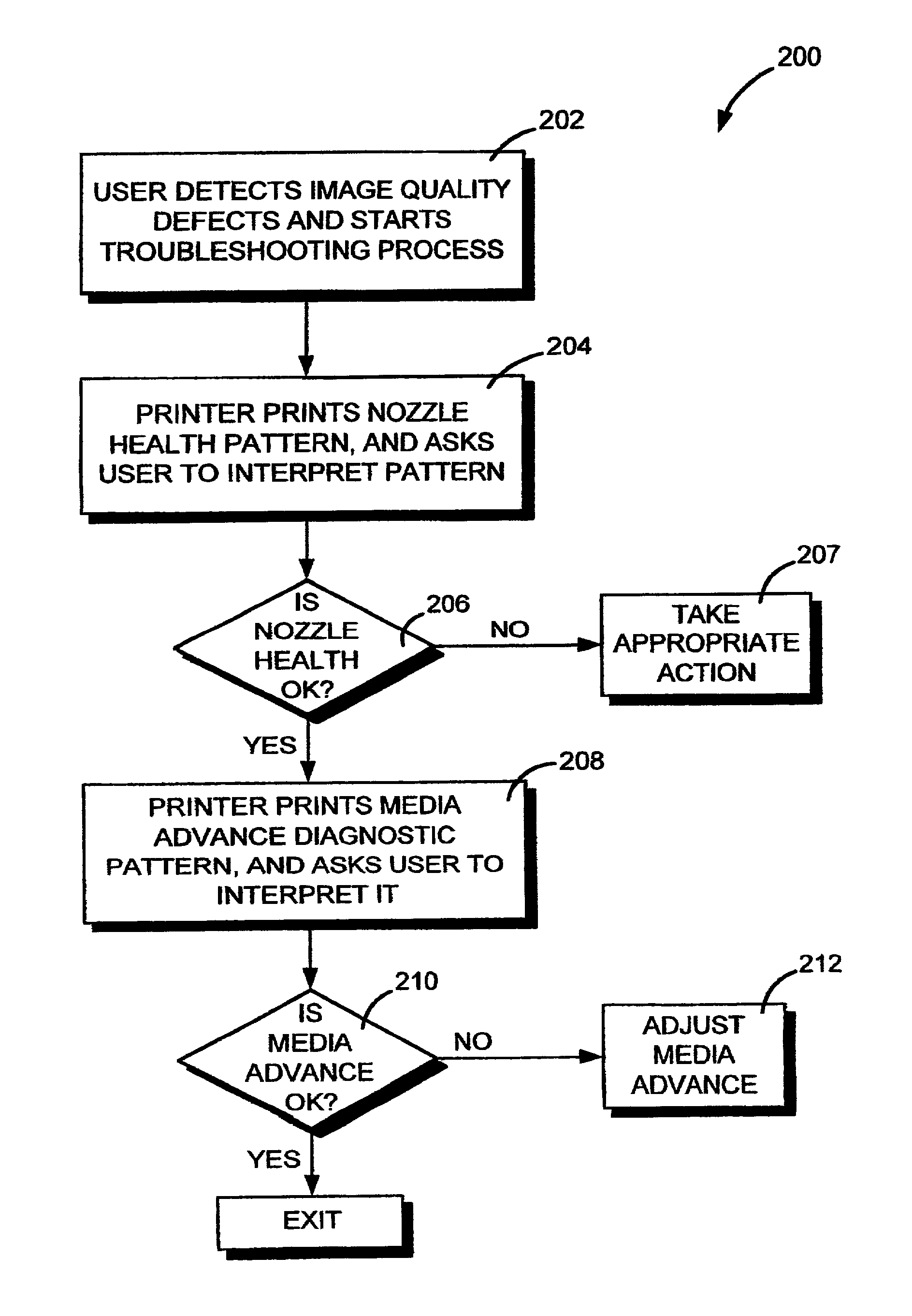
Diagnostic for visual detection of media advance errors
a technology of error detection and imaging, applied in the field of imaging printers, can solve problems such as systemic nozzle contribution, and achieve the effects of increasing the number of media advances, increasing the effect of accumulated errors, and increasing the apparent visual
- Summary
- Abstract
- Description
- Claims
- Application Information
AI Technical Summary
Benefits of technology
Problems solved by technology
Method used
Image

Examples
Embodiment Construction
[0026]Exemplary embodiments of this invention will be described with respect to large format printers, although the invention can also be practiced on other types of printers.
[0027]Commonly assigned U.S. Pat. No. 5,835,108, entitled CALIBRATION TECHNIQUE FOR MISDIRECTED INKJET PRINTHEAD NOZZLES, describes an exemplary large format color inkjet printer / plotter which can employ the recent invention. FIGS. 1-8 and the following description of these figures are generally taken from this patent, the entire contents of which are incorporated herein by this reference.
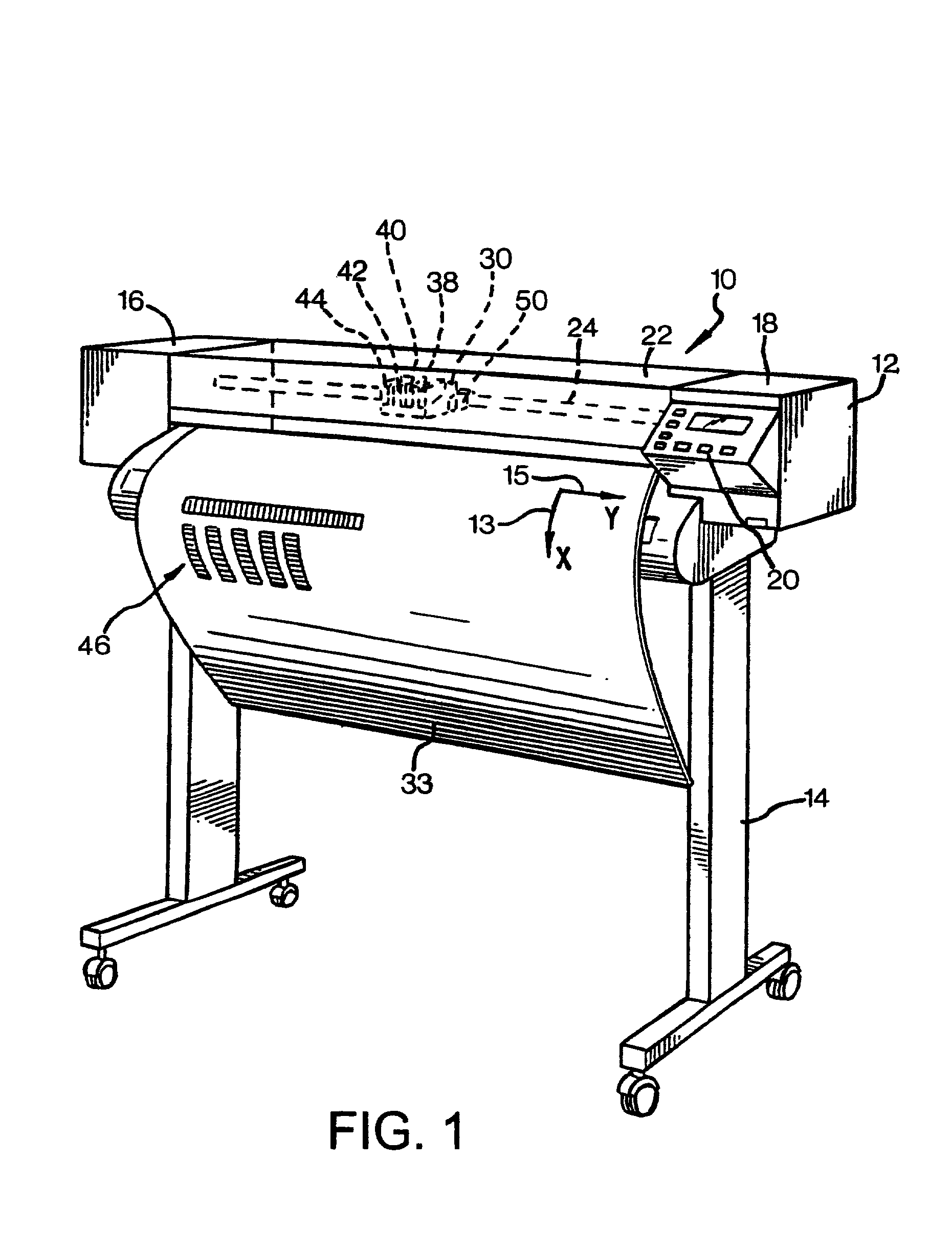
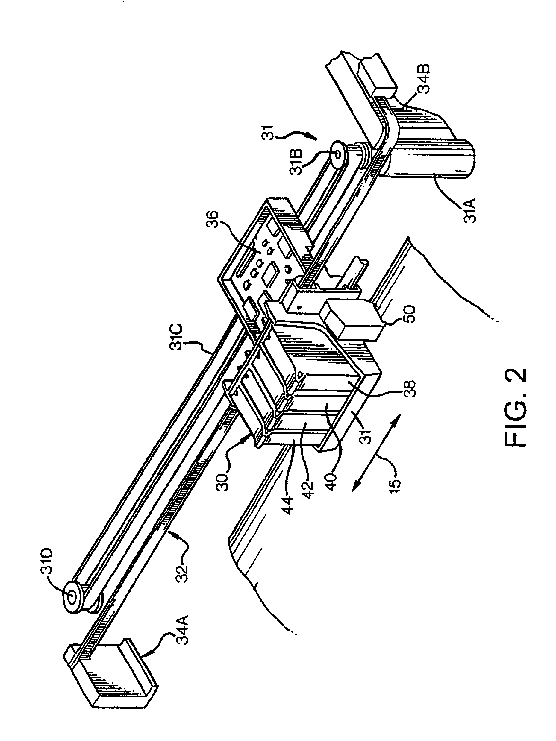
[0028]FIG. 1 is a perspective view of an inkjet printer / plotter 10 having a housing 12 mounted on a stand 14. The housing has left and right drive mechanism enclosures 16 and 18. A control panel 20 is mounted on the right enclosure 18. A carriage assembly 30, illustrated in phantom under a cover 22, is adapted for reciprocal motion along a carriage bar 24, also shown in phantom. The position of the carriage assembly 30 in a ho...
PUM
 Abstract
Description
Claims
Application Information