
Magnetic conductive track and lighting equipment

A conductive track and magnetic attraction technology, applied in the field of lighting, can solve the problems of complex assembly process and many overall design parts, and achieve the effect of simplified assembly process, less overall parts and low cost

Pending Publication Date: 2021-07-23
OPPLE LIGHTING +1
View PDF0 Cites 2 Cited by
  • Summary
  • Abstract
  • Description
  • Claims
  • Application Information

AI Technical Summary

Problems solved by technology

[0006] The embodiment of the present application provides a magnetic conductive track and lighting equipment, which is used to solve the problem that copper bars, aluminum substrate PCBs or resin PCBs are used as conductive components in the existing low-voltage guide rail technology. The iron plate is built into the back as a magnetic component; and the aluminum substrate PCB or resin PCB also needs to add an iron plate built into the back as a magnetic component. The overall design has many parts and the assembly process is also complicated.

Method used


Image

  • Magnetic conductive track and lighting equipment
  • Magnetic conductive track and lighting equipment
  • Magnetic conductive track and lighting equipment

Examples


Embodiment Construction

[0067] In order to make the purpose, technical solution and advantages of the present application clearer, the technical solution of the present application will be clearly and completely described below in conjunction with specific embodiments of the present application and corresponding drawings. Apparently, the described embodiments are only some of the embodiments of the present application, rather than all the embodiments. Based on the embodiments in this application, all other embodiments obtained by persons of ordinary skill in the art without making creative efforts belong to the scope of protection of this application.

[0068] The technical solutions provided by various embodiments of the present application will be described in detail below in conjunction with the accompanying drawings.

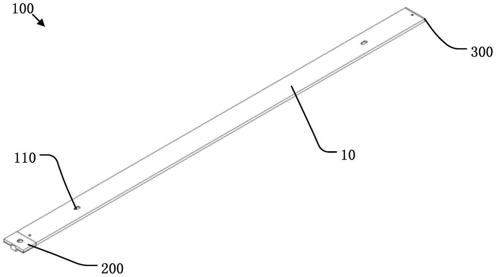
[0069] Such as Figure 3 to Figure 5 As shown, the embodiment of the present application discloses a magnetically attractive conductive track 100 , which is long and flat, used to...


PUM


Abstract

The embodiment of the invention discloses a magnetic attraction conductive track and lighting equipment, the magnetic attraction conductive track is used for being assembled on a mounting base and can form magnetic attraction and electric connection with a lighting device, and the magnetic attraction conductive track comprises a mounting main body and a pair of conductive substrates. The conductive substrate comprises a magnetic attraction layer, an insulating layer and a conductive layer, the magnetic attraction layer faces the mounting side of the mounting main body, the conductive layer faces the connecting side of the mounting main body and is exposed to the outside so that the lighting device can take electricity, and the magnetic attraction layer can be used for being connected with the lighting device in an attraction mode. According to the magnetic attraction conductive track, the conductive substrate is used, the conductive function is achieved, meanwhile, the magnetic attraction attribute is achieved, the conductive structure and the magnetic attraction structure are integrated, the assembly process is simplified, and the cost is lower; meanwhile, the electricity taking mode of the conductive substrate on the lower portions of the two sides of the guide rail can facilitate visual detection.

Description

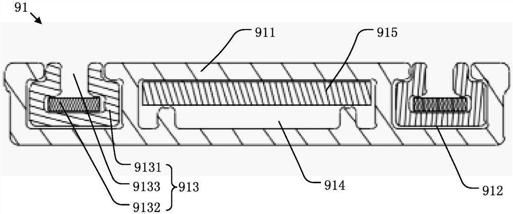
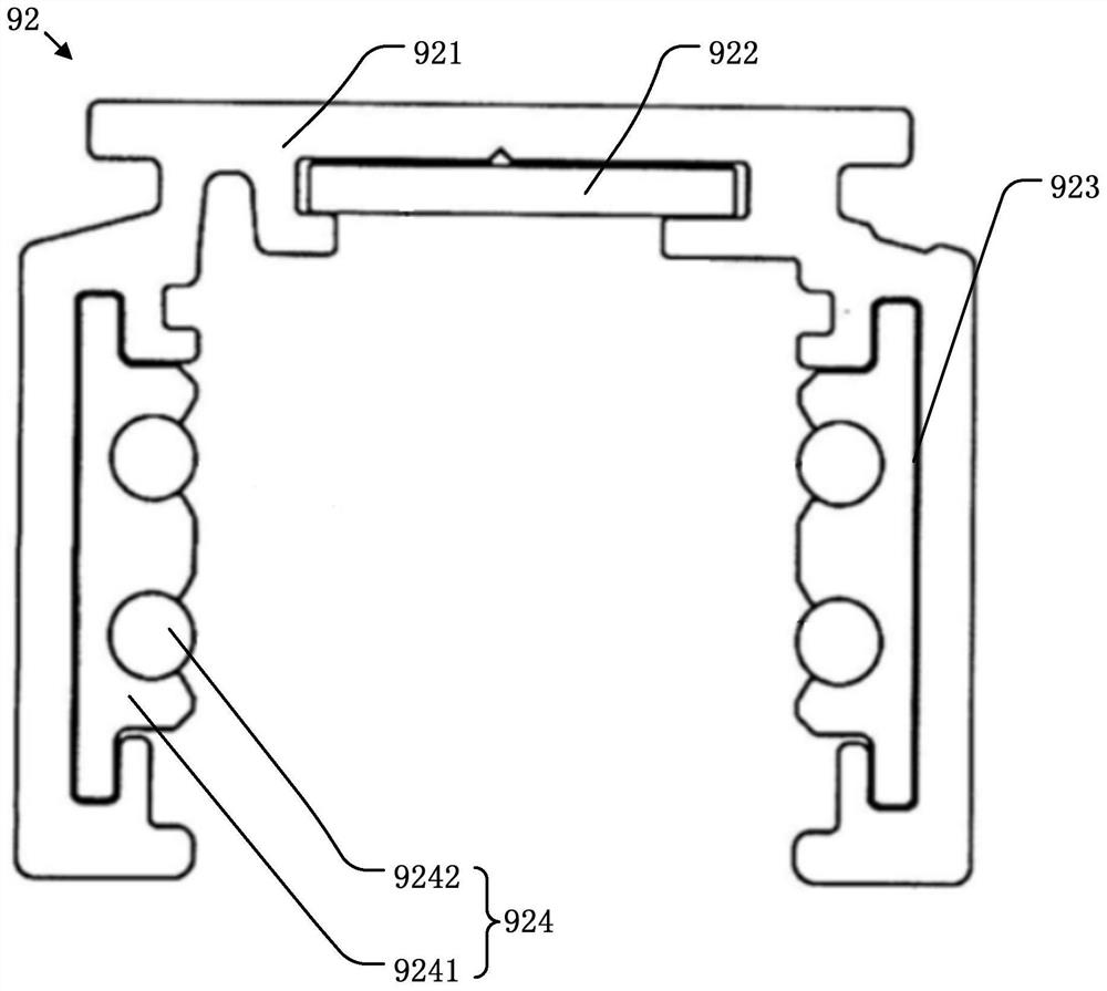
technical field [0001] The present application relates to the technical field of lighting, and in particular to a magnetically attracting conductive track and lighting equipment for magnetically absorbing and electrically connecting electrical devices. Background technique [0002] Track lights mainly include guide rails (conductive tracks) fixed on the ceiling or walls and various lamp bodies that can slide along the guide rails, which can be spotlights, line lights, etc. At present, the low-voltage guide rails commonly used in the market basically use copper strips, aluminum substrate PCBs or resin PCBs as conductive components. [0003] Such as figure 1 as shown, figure 1 It is a structural schematic diagram of a low-voltage guide rail adopting top power supply in the prior art. The guide rail 91 includes a main body 911 . Along the width direction of the guide rail 91 , the cross section of the main body 911 is roughly flat. Two accommodating grooves 912 are recessed ...

Claims


Application Information

Patent Timeline
Patent Type & Authority Applications(China)
IPC IPC(8): F21S8/00F21V21/35F21V23/06F21V21/096
CPCF21S8/00F21V21/35F21V23/06F21V21/096H01R25/147H01R25/142H01R13/6205F21Y2103/20F21S8/038F21V21/005
Inventor 杨涛谢建民
Owner OPPLE LIGHTING
Learn More