Wheel bearing unit

a technology of bearing unit and bearing shaft, which is applied in the direction of bearing unit rigid support, mechanical equipment, transportation and packaging, etc., can solve the problems of affecting the driving characteristics of the vehicle, affecting the operation of brake wear and brakes, and a relatively low bearing stiffness of known wheel bearing units, so as to increase the bearing tilt stiffness, and increase the bearing stiffness

Active Publication Date: 2008-08-19
INA SCHAEFFLER KG
View PDF14 Cites 7 Cited by
  • Summary
  • Abstract
  • Description
  • Claims
  • Application Information

AI Technical Summary

Benefits of technology

[0020]The bearing stiffness, which is markedly increased as a result of the invention by about 40% relative to the prior art, leads to increased bearing tilt stiffness. The increased bearing tilt stiffness leads to lower load-dependent deformations on the wheel bearing unit and thus to lower deformations on the brake disks.

Problems solved by technology

Known wheel bearing units have a relatively high weight and a relatively low bearing stiffness.
The lower the bearing stiffness, the more the loads induce tiltings of the wheel system, which adversely affect the driving characteristics of the vehicle, especially when cornering, and adversely affect brake wear and brake functioning.

Method used


Image

  • Wheel bearing unit
  • Wheel bearing unit
  • Wheel bearing unit

Examples


Embodiment Construction

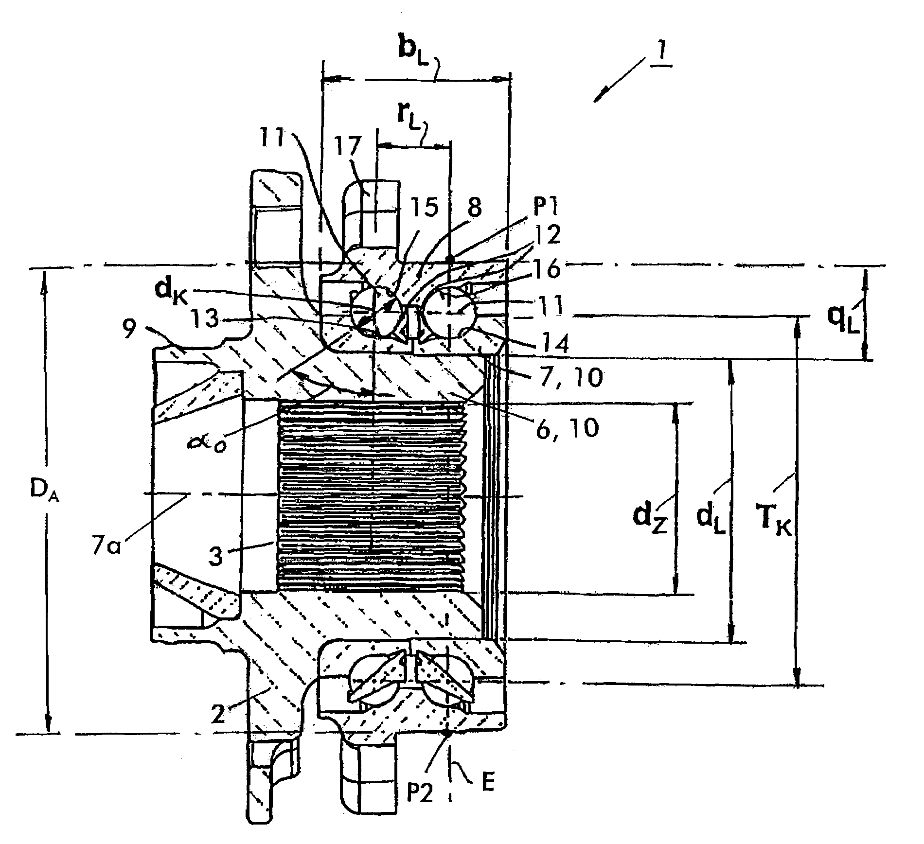
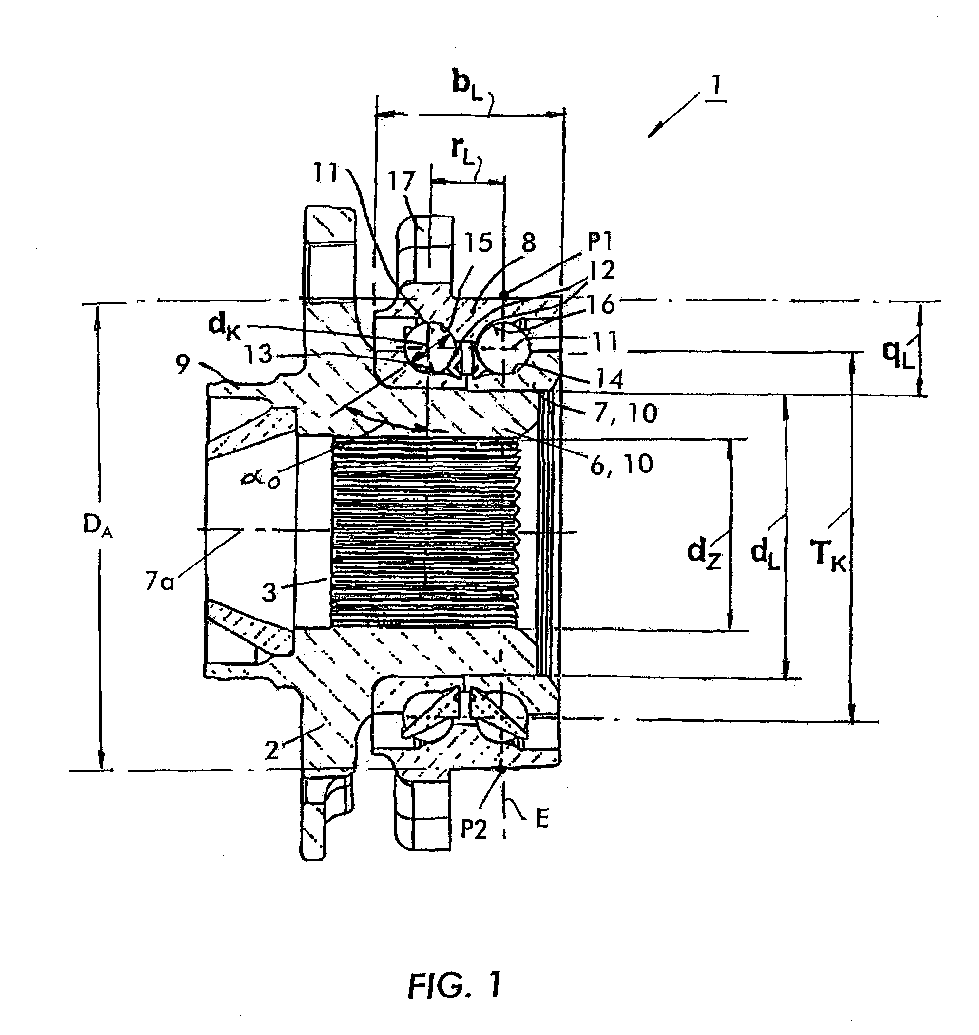
[0036]The inner toothing 3 on the wheel hub 2 is designed for engagement in an outer toothing of a drive journal (not represented). The wheel hub 2 is mounted rotatably in the outer part 8 and has a flange 9 for the fastening of a vehicle wheel (not represented) and of a brake disk. On the wheel hub 2 are seated the inner parts 10 in the form of inner rings 6 and 7, which respectively have an outer raceway 13 and 14 for the rolling contact with a respective row of rolling elements 11 in the form of balls. The rolling elements 11 of a row are guided in a cage 12. The outer part 8 replaces as a flange element the traditional outer ring(s) and has, for this purpose, the inner raceways 15 and 16 for the rolling contact with the rolling elements 11. The outer part 8 is provided with a flange 17 for the vehicle-sided fastening of the wheel bearing unit 1.

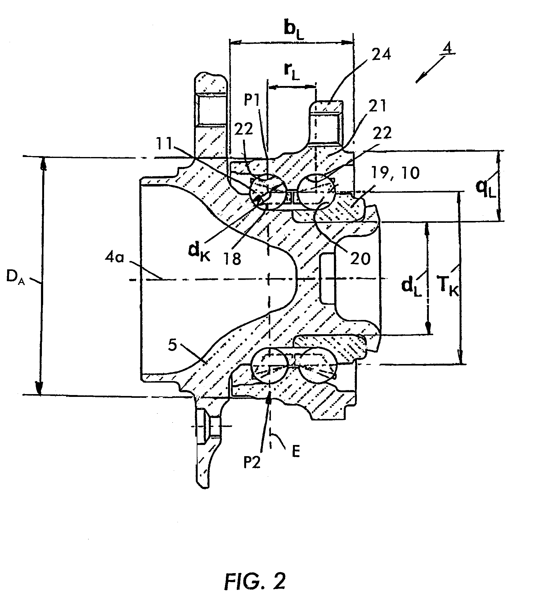
[0037]The wheel bearing unit 4 for non-driven wheels has a wheel hub 5 on which an inner raceway 18 for a row of rolling elements 11 is ...


PUM


Abstract

A wheel bearing unit having at least one outer part, at least one inner part and having at least two rows of rolling elements between the outer part and the inner part, on the outer part at least one inner raceway, and on the inner part at least one outer raceway for the rolling elements of a row.

Description

CROSS REFERENCE TO RELATED APPLICATIONS[0001]This application claims the benefit of the United States Provisional Patent Application No. 60 / 655,337 filed on 22 Feb. 2005 and German Application No. 10 2004 055 786.1, filed Nov. 18, 2004, the disclosures of which is hereby incorporated by reference.FIELD OF THE INVENTION[0002]The invention relates to a wheel bearing unit having at least one outer part, at least one inner part and having at least two rows of rolling elements between the outer part and the inner part, on the outer part at least one inner raceway respectively being configured, and on the inner part at least one outer raceway for the rolling elements of a row respectively being configured.BACKGROUND TO THE INVENTION[0003]Known wheel bearing units have a relatively high weight and a relatively low bearing stiffness. The bearing stiffness is here the resistance which the unit puts up against elastic deflections provoked by loads. From the bearing stiffness a tilt stiffness ...

Claims


Application Information

Patent Timeline
Patent Type & Authority Patents(United States)
IPC IPC(8): F16C13/00F16C19/00B60B27/00F16C19/18
CPCB60B27/00B60B27/0005B60B27/0026B60B27/0084F16C19/186F16C19/185B60B27/0094F16C2326/02F16C2240/80F16C2240/40F16C19/18
Inventor NIEBLING, PETERMASUR, ERNSTRUOFF, GOTTFRIED
Owner INA SCHAEFFLER KG
Why Eureka
Try Eureka