Electrical connector and electrical plug and socket connection

a technology of electrical connectors and sockets, applied in the direction of hose connections, coupling device connections, mechanical equipment, etc., can solve the problems of increased force expenditure, large tightening moment, union nuts being tightly screwed with tools, etc., and achieve the effect of preventing damage to the sealing elemen

Active Publication Date: 2008-08-19
IMF ELECTRONIC GMBH
View PDF4 Cites 7 Cited by
  • Summary
  • Abstract
  • Description
  • Claims
  • Application Information

AI Technical Summary

Benefits of technology

[0009]An aspect of this invention is to provide an electrical connector and an electrical plug and socket connection, similar to that described above, in which the aforementioned disadvantages are avoided, especially where damage of the sealing element is prevented.
[0010]This aspect can be realized by providing a stop that limits the maximum path by which the union nut can be screwed onto the mating connector such that when the union nut is screwed on, the elastic sealing element is compressed as desired, but is not damaged or destroyed. The stop in accordance with this invention thus forms a protective mechanism against “overpressing” of the sealing element. The stop also limits the maximum compressive force on the sealing element to an allowable value even with a large tightening moment.
[0011]In a first configuration of the invention, the stop is implemented by a corresponding geometrical configuration of the electrical connector. The stop can be made either on the inside surface of the union nut or on the outside periphery of the contact carrier. In two versions disclosed herein, the stop limits the maximum screw-down path of the union nut, by which it is ensured that a given axial distance between the second face side of the collar on the contact carrier and the face side of the mating connector is maintained. The space between the face side of the mating connector and the second face side of the collar of the contact carrier, which is limited in the radial direction by the contact carrier and the inside of the union nut, then can not fall below a given value. A return space is formed for the elastic sealing element, with this return space being dimensioned such that on the one hand the desired compression of the sealing element occurs, so that it performs its sealing function, but on the other hand “overpressing” of the sealing element is prevented.
[0014]In the second embodiment, the vibration guard is formed by the additional component and the union nut. In this case, the vibration guard is made such that the required force when the union nut is screwed tight is less than in unscrewing. The additional component is thus used both as a stop for limiting the maximum screw-down path and also as a vibration guard. The additional component is preferably made of metal so that even when the union nut which likewise consists of metal is repeatedly screwed down and unscrewed, the vibration guard does not wear. The vibration guard implemented between the additional component and the union nut is thus durable and resists wear.
[0017]As described above, in this connection the additional component, i.e. the stop ring or stop sleeve, is part of the vibration guard. In this regard, it is preferable that the stop ring or the stop sleeve is provided with axially and / or radially projecting, ramp-shaped projections or spring tongues. These form a direction-dependent vibration guard together with the union nut. In this case, the stop ring and the stop sleeve are preferably made of metal. The ramp-shaped projections or spring tongues on the one hand enable the union nut to be screwed down relatively easily, while on the other hand, when unscrewing in the opposite direction, the steep angle of the projection or spring tongue makes loosening difficult.
[0021]In the electrical plug and socket connection in accordance with the invention, the stop is preferably implemented by a shoulder being formed on the thread base of the mating connector. The shoulder limits, on one hand, the maximum screw-in depth of the union nut, and, on the other hand, guarantees a sufficient return space for the elastic sealing element, so that the desired compression occurs, but without “overpressing” of the sealing element.

Problems solved by technology

One disadvantage in known connectors is that an increased expenditure of force is necessary due to the vibration guard when the union nut is screwed into or onto the outside sleeve of the mating connector.
In practice, this often leads to the union nut being screwed tightly with a tool.
As a result, the tightening moment can be so great that damage to the electrical connector, especially overly strong compression, i.e. “overpressing” of the elastic sealing element, occurs.
“Overpressing” of the sealing element can lead to the sealing element being damaged so that the sealing element no longer maintains its sealing action or, in any case, no longer reliably and permanently maintains its sealing action.

Method used


Image

  • Electrical connector and electrical plug and socket connection
  • Electrical connector and electrical plug and socket connection
  • Electrical connector and electrical plug and socket connection

Examples


Embodiment Construction

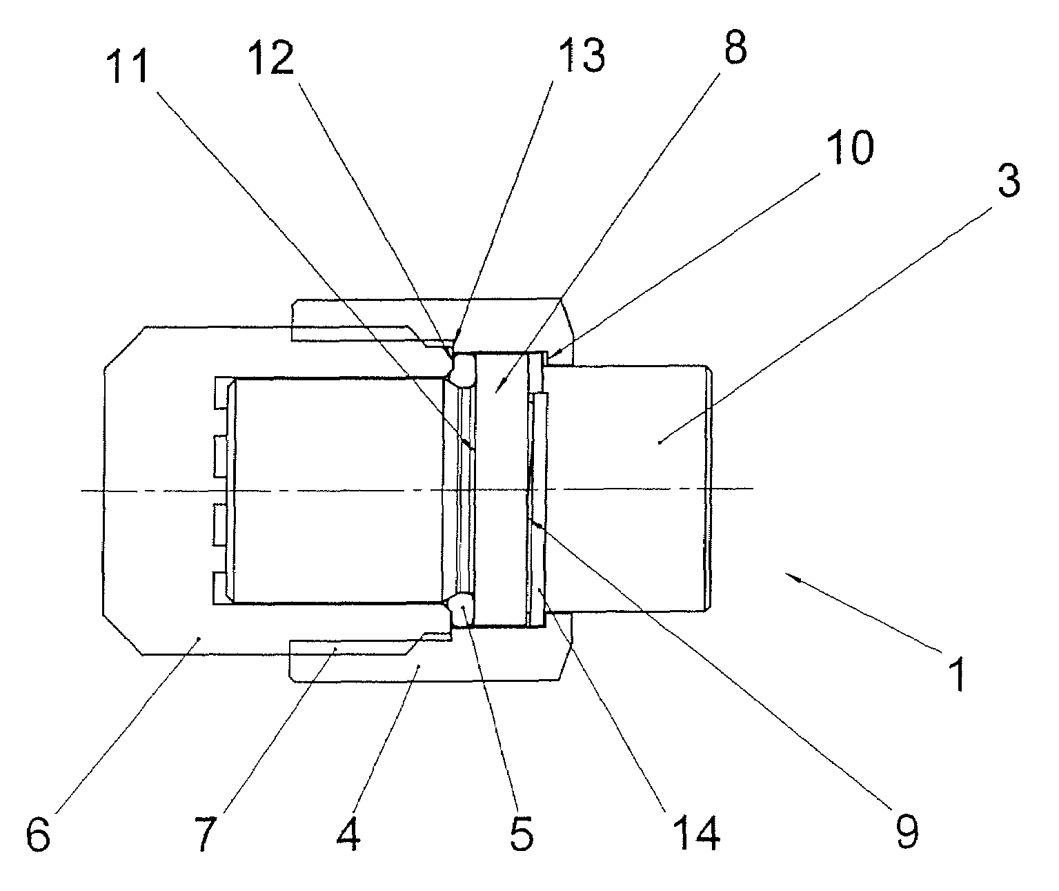
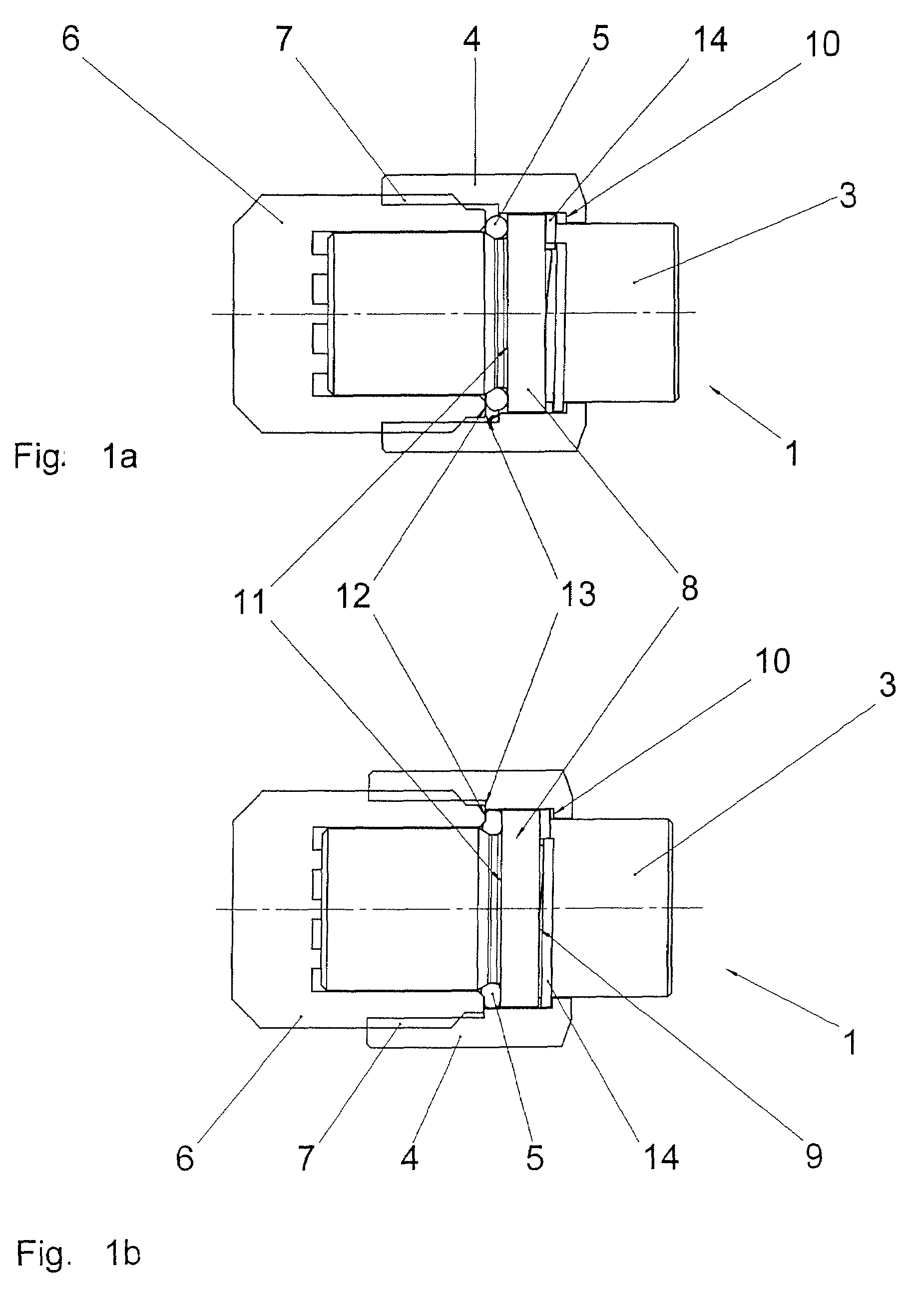
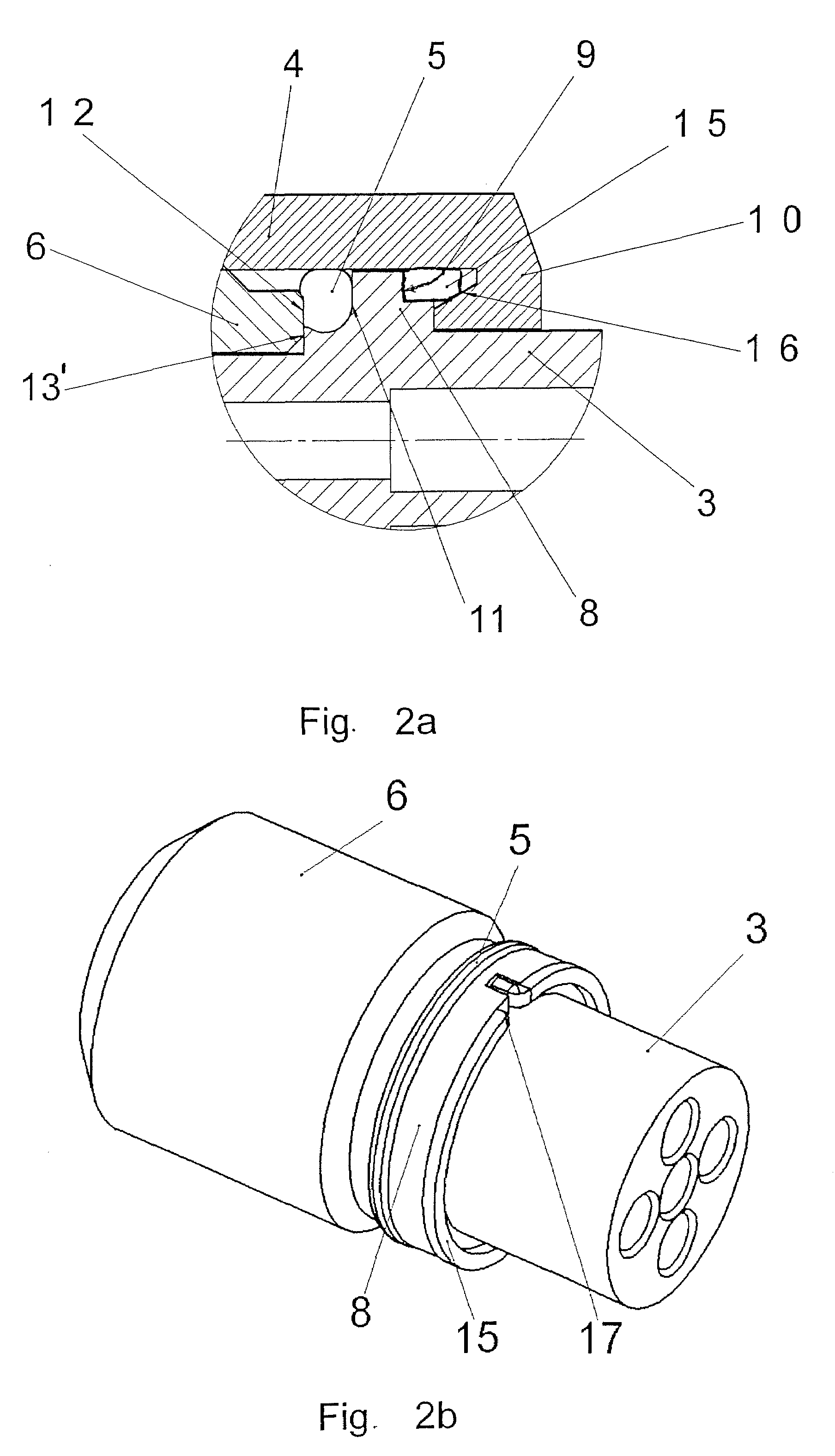
[0049]The figures show different versions of an electrical connector 1 and individual components of such an electrical connector 1, all in accordance with this invention. The electrical connector 1 has a handle body 2 (seen in FIG. 12), which surrounds a cable set (not shown), a contact carrier 3, a union nut 4 that is rotatable and axially displaceable to a limited degree on the contact carrier 3, and an elastic sealing element 5 that is located on the contact carrier 3 preferably in the form of a gasket. The electrical connector 1 can be connected to a corresponding mating connector 6 by screwing the union nut 4 onto a thread 7 formed on the outside sleeve of a mating connector 6.

[0050]As is apparent from FIGS. 1 to 7, the contact carrier 3 has a peripheral collar 8 which is located roughly in the middle area of the contact carrier 3. The peripheral collar 8 has a first face side 9, which is used as a stop for an end-side shoulder 10 of the union nut 4. By this arrangement, when t...


PUM


Abstract

An electrical connector connects to a mating connector by a rotatable union nut that is axially displaceable on a contact carrier with a sealing element therebetween. Damage to the sealing element is prevented by a stop that limits the maximum path by which the union nut can be screwed onto the mating connector, such that when the union nut is screwed on, the elastic sealing element is intentionally compressed, but is not damaged or destroyed. A vibration guard can also be provided in the connection.

Description

BACKGROUND OF THE INVENTION[0001]1. Field of the Invention[0002]The invention relates to an electrical plug and socket connection with a connector and a mating connector.[0003]2. Description of Related Art[0004]Electrical plug and socket connections typically consist essentially of two parts, the electrical connector and the mating connector. Both the connector and the mating connector have a contact carrier with corresponding contacts, which are either contact pins or corresponding sockets. Depending on whether the contact pins or the sockets are located in the respective contact carrier, the pertinent connecting part is called a plug or a socket. For purposes of simplicity of description, and without the invention being limited thereto, it is assumed herein that the contact carrier of the connector has sockets, while the contact pins are located in the contact carrier of the pertinent mating connector. Of course, one of ordinary skill in the art would understand that the component...

Claims


Application Information

Patent Timeline
Patent Type & Authority Patents(United States)
IPC IPC(8): H01R13/62H01R4/38
CPCH01R13/622H01R13/5219
Inventor MEHNERT, WOLFGANGFROESE, BERNDHARTRAMPF, ANDREASOHLINGER, THOMAS
Owner IMF ELECTRONIC GMBH
Why Eureka
Try Eureka