
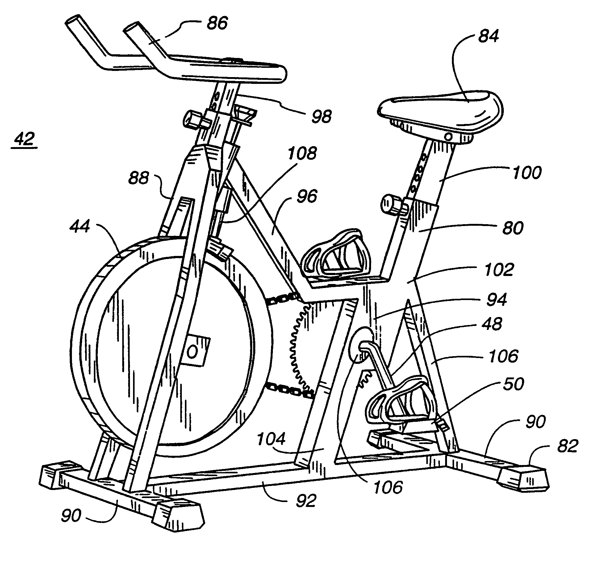
Frame for an exercise bicycle

a frame and exercise technology, applied in the direction of gymnastic exercise, slip coupling, coupling, etc., can solve the problems of inconvenient direct drive relationship between the flywheel and the drive train

Inactive Publication Date: 2008-08-19
NAUTILUS INC
View PDF142 Cites 22 Cited by
  • Summary
  • Abstract
  • Description
  • Claims
  • Application Information

AI Technical Summary

Benefits of technology

Enables riders to stop pedaling, pedal backwards, or rotate more slowly than the flywheel, providing a smooth and efficient exercise experience by allowing the pedals to turn independently of the flywheel, thus addressing the limitations of direct drive systems.

Problems solved by technology

The direct drive relationship between the flywheel and the drive train is also a drawback of exercising on this type of bicycle.
The direct drive relationship is inconvenient when the rider wishes to quickly stop the pedals, or loses the pedaling rhythm required to keep up with the rotating flywheel.

Method used


Image

  • Frame for an exercise bicycle
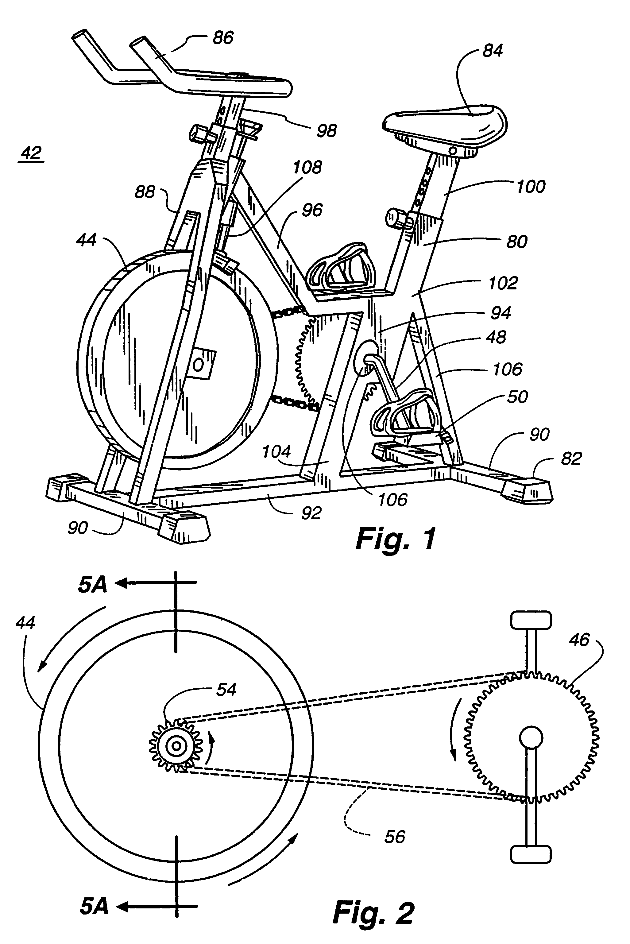
  • Frame for an exercise bicycle
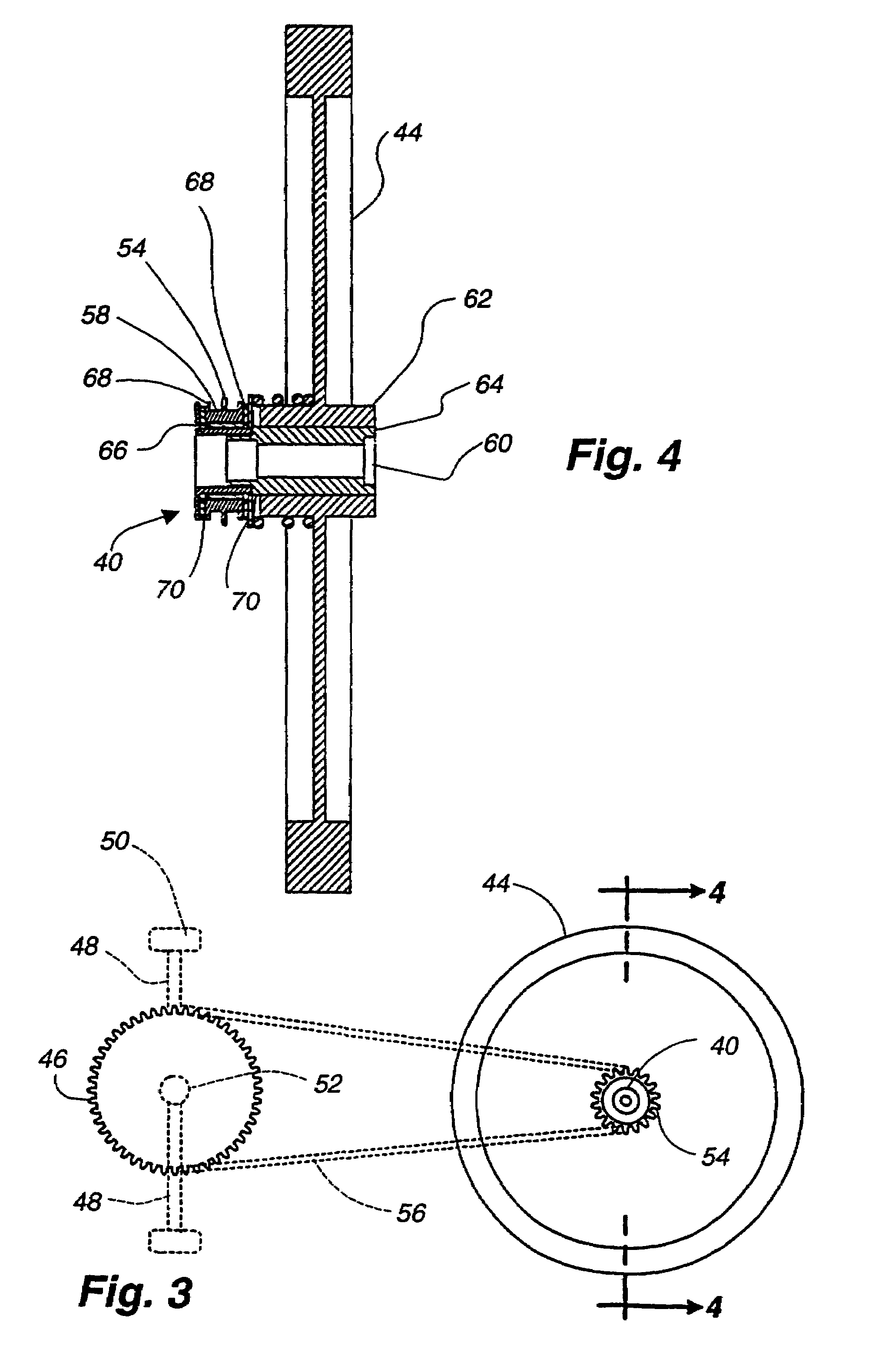
  • Frame for an exercise bicycle

Examples


first embodiment

[0084]An alternative embodiment of the free wheel clutch mechanism is shown in FIGS. 17–20. This alternative embodiment works on the same principle as the first embodiment described above, except basically replaces the single large spring surrounding the hub 150 with the plurality of smaller springs 152 positioned between the flywheel 154 and the inner clutch plate 156. These plurality of springs 152 act to push the inner clutch plate 156 outwardly as the clutch material 158 wears down from use. As can best be seen in FIGS. 19 and 20, each of the plurality of springs surrounds a guide rod 160 mounted to the flywheel 154 which is received in a guide bore 162 mounted to and extending from the inside side of the inner clutch plate 156. The sliding interaction between the guide rod 160 and the guide bore 162 helps ensure that the inner clutch plate 156 is squarely moved outwardly under the bias of the springs as the clutch material wears as a result of use. The interaction of the guide ...

third embodiment

[0095]Another alternative embodiment is disclosed in FIG. 24 which shows two Belleville washers 240, 242 positioned back to back to allow for a longer adjustment stroke due to the wear of the inner and outer clutch material washers 244, 246. In this third embodiment the outwardly extending flange 248 of the second retainer 250 is enlarged to engage the outer rim of the second Belleville washer 240. Belleville washers are very stiff and provide a great deal of force through the length of their extension.

[0096]Another alternative embodiment is disclosed in FIGS. 25–26. This fourth alternative embodiment utilizes a band-brake to create the frictional break-free force. The band-brake 260 includes a retainer 262 fixed to the flywheel 264 through which is positioned a spring loaded adjustment screw 266 which attaches to a housing 268. The housing includes two guide slots 270 for slidably receiving tabs 272 formed on the flywheel. The housing is also fixed to the opposite ends of a belt 27...


PUM


Abstract

An exercise bicycle including a frame having a seat and handlebars, a high-inertia flywheel having a hub at a center of rotation, the flywheel being rotatably supported on the frame at the hub, and a drive train including a drive sprocket, a crank arm attached to and extending from the drive sprocket, and a pedal attached to the crank arm, the drive train being rotatably supported by the frame. The drive train also includes a slave sprocket fixed to the flywheel at the hub, with the drive and slave sprockets connected in a direct-drive relationship, the drive train driveable in a forward and rearward directions to cause the flywheel to rotate. A clutch mechanism is positioned in engagement with the slave sprocket and the hub to create a frictional engagement between the sprocket and the hub, and to establish a break-free force threshold. When the drive train is actuated in the forward direction, the slave sprocket and the hub move together, and when the drive train is actuated in the rearward direction under the influence of a force greater than the break-free force threshold, the clutch mechanism slips between the slave sprocket and the hub, allowing the slave sprocket and the flywheel to move independently of one another. The clutch mechanism including a spring tensioner whereby the break-free force may be adjusted.

Description

CROSS-REFERENCE TO RELATED APPLICATIONS[0001]This application is a continuation of U.S. application Ser. No. 09 / 803,630 filed Mar. 9, 2001, which is a continuation-in-part of U.S. application Ser. No. 09 / 379,560 filed Aug. 23, 1999, now U.S. Pat. No. 6,641,507 B1, which is a continuation of U.S. application Ser. No. 08 / 919,695 filed Aug. 28, 1997, now U.S. Pat. No. 5,961,424, which claims the benefit of U.S. provisional application No. 60 / 038,726 filed Feb. 18, 1997, which are all hereby incorporated by reference as if fully disclosed herein.FIELD OF THE INVENTION[0002]This invention relates generally to free wheeling devices, and more particularly to a free wheel clutch mechanism useful with crank operated exercise bicycles employing an inertia flywheel.BACKGROUND[0003]The benefit of exercising on a direct drive exercise bicycle is well known. Direct drive exercise bicycles typically utilize a high-inertia flywheel driven by a fixed-gear drive train. The flywheel is driven by the r...

Claims


Application Information

Patent Timeline
Patent Type & Authority Patents(United States)
IPC IPC(8): A63B69/16A63B21/00A63B21/22A63B22/00A63B22/08B62M1/10F16D7/02F16D41/24
CPCA63B21/157A63B21/225A63B22/0605F16D7/025F16D41/24B62M1/10A63B2225/09A63B2022/0658A63B69/16
Inventor WARNER, PATRICKHARDING, MICHAEL H.WU, MU-CHUANBAKER, ANDY
Owner NAUTILUS INC
Features
  • Generate Ideas
  • Intellectual Property
  • Life Sciences
  • Materials
  • Tech Scout
  • Unparalleled Data Quality
  • Higher Quality Content
  • 60% Fewer Hallucinations
Learn More