Wearable joint driving device

a driving device and wearable technology, applied in the field of wearable joint driving devices, can solve the problems of generating wrinkles, looseness or the like in clothes, unable to obtain a sufficient operating amount and driving force for practical use, and unable to obtain a sufficient operating amount and driving force. practical use, the effect of increasing the operating amount and driving for

Inactive Publication Date: 2008-08-19
TOKYO UNIVERSITY OF SCIENCE
View PDF8 Cites 52 Cited by
  • Summary
  • Abstract
  • Description
  • Claims
  • Application Information

AI Technical Summary

Benefits of technology

[0004]The present invention has been made with a view toward solving the above problem. It is an object of the present invention to provide a wearable joint driving device capable of achieving an improvement in driving force transmission efficiency and an increase in operating amount and driving force.

Problems solved by technology

However, in the above conventional wearable joint driving device, a force from the pneumatic actuators acts on the link bodies of the clothes formed of a flexible material such as cloth, so that wrinkles, looseness, or the like may be generated in the clothes, and the clothes may be deviated with respect to the human body.
Accordingly, there is a fear of the operating amount of the pneumatic actuators not being properly transmitted to the human body, making it impossible to obtain a sufficient operating amount and driving force for practical use.

Method used


Image

  • Wearable joint driving device
  • Wearable joint driving device
  • Wearable joint driving device

Examples


embodiment 1

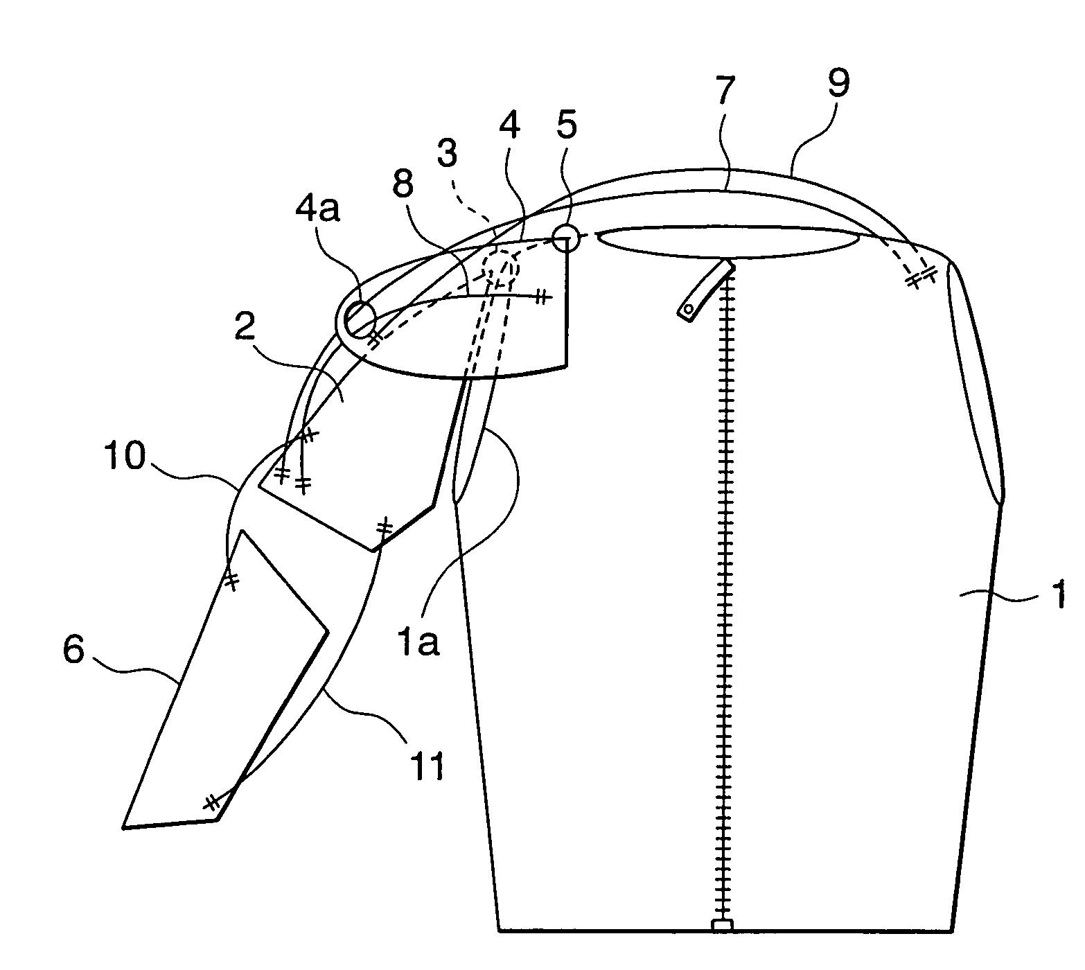
[0024]FIG. 1 is a front view of a wearable joint driving device according to Embodiment 1 of the present invention. In this example, the device shown is of a type which is worn by the upper part of a human body and which drives a shoulder joint portion and an elbow joint portion of one arm. Further, in this example, what is driven is a part of a human body. The torso (body) constitutes a first wearing body, the upper arm constitutes a second wearing body, and the forearm constitutes a third wearing body. The body and the upper arm are connected by the shoulder joint portion, and the upper arm and the forearm are connected by the elbow joint portion.

[0025]In the drawing, a torso frame 1 as a first frame member is put on the torso. The torso frame 1 is provided with a sleeve opening 1a through which the arm is to be passed. Further, inside the torso frame 1, there is provided a fixation belt (not shown) for preventing movement of the torso frame 1 relative to the torso.

[0026]An upper ...

embodiment 2

[0047]Next, FIG. 7a is a side view of a wearable joint driving device according to Embodiment 2 of the present invention, FIG. 7b is a sectional view taken along the line A-A of FIG. 7a, FIG. 7c is a sectional view showing a state in which air has been supplied to the frame tube of FIG. 7b, and FIG. 8 is a block diagram showing the construction of the operation control portion of the wearable joint driving device of FIG. 7a. In this example, the device shown is of the type which is put on a knee portion of the human body to cause the knee joint to make bending and stretching motions. Further, a thigh portion and a lower leg portion, to which this device is put on, are rotatably connected at the knee portion constituting the joint portion.

[0048]In the drawings, a frame member 21 has a support member 22 on which the thigh portion and the lower leg portion are placed, and first and second frame tubes 23, 24 contained in the support member 22. Air is supplied to the first and second fra...

embodiment 3

[0053]Next, FIG. 9 is a perspective view, as seen obliquely from the front right-hand side, of a wearable joint driving device according to Embodiment 3 of the present invention; FIG. 10 is a perspective view, as seen obliquely from the front left-hand side, of the wearable joint driving device of FIG. 9; FIG. 11 is a perspective view, as seen obliquely from the rear left-hand side, of the wearable joint driving device of FIG. 9; and FIG. 12 is an exploded perspective view showing the left-arm side frame construction of the wearable joint driving device of FIG. 9. While FIGS. 9 through 11 only show an actuator for driving the left arm for the sake of simplicity, in reality, there is arranged, symmetrically therewith, an actuator for driving the right arm.

[0054]In the drawings, a torso frame 31 as a first frame member is put on the torso. The torso frame 31 is provided with a head portion insertion hole 31a through which the head portion is to be passed. Further, the torso frame 31 h...


PUM


Abstract

Provided is a wearable joint driving device in which a plurality of frame members are attached to a wearing body so as to be in contact with the outer surface of the wearing body. Between the frame members, there is mounted a fluid pressure type actuator. The fluid pressure type actuator has an expansion / contraction member and a net-like covering member covering the outer periphery of the expansion / contraction member. The fluid pressure type actuator undergoes a reduction in length through expansion of the expansion / contraction member to thereby generate a driving force. The frame members have a predetermined level of rigidity.

Description

TECHNICAL FIELD[0001]The present invention relates to a wearable joint driving device worn by a human body or the like to allow a joint portion to make a movement.BACKGROUND ART[0002]JP 2002-103270 A discloses a wearable joint driving device worn by a human body to allow a joint portion to make a movement. In the conventional wearable joint driving device, a plurality of pneumatic actuators, which are reduced in length through air supply to generate a driving force, are mounted to clothes worn by the human body. That is, in the above-mentioned device, by reducing the length of the pneumatic actuators, a contraction force is exerted between link bodies formed in the clothes, thereby driving joint portions of the human body.[0003]However, in the above conventional wearable joint driving device, a force from the pneumatic actuators acts on the link bodies of the clothes formed of a flexible material such as cloth, so that wrinkles, looseness, or the like may be generated in the clothes...

Claims


Application Information

Patent Timeline
Patent Type & Authority Patents(United States)
IPC IPC(8): A61F5/00A61F5/01A61H1/02B25J9/00B25J9/14F15B15/10
CPCA61F5/0102A61H1/0277A61H1/0281F15B15/103B25J9/0006B25J9/142A61H23/04A61H2201/165
Inventor KOBAYASHI, HIROSHISATO, YUTAKAHIRAMATSU, KAZUAKIKONAMI, MAKOTOMATSUSHITA, TAISUKEMUROMACHI, MASAAKIUCHIMURA, AKITAKA
Owner TOKYO UNIVERSITY OF SCIENCE
Why Eureka
Try Eureka