Automobile antenna

a technology for antennas and vehicles, applied in the direction of antennas, antenna details, antenna adaptation in movable bodies, etc., can solve the problems of aging and deterioration under environmental conditions, affecting the appearance of the entire antenna, and not being able to avoid the effect of appearance degradation

Inactive Publication Date: 2008-08-19
CLARION CO LTD
View PDF9 Cites 21 Cited by
  • Summary
  • Abstract
  • Description
  • Claims
  • Application Information

AI Technical Summary

Benefits of technology

[0011]With such construction, the pad member is not mounted and fixed to the cover member but the pad member is mounted and fixed so as to embrace a face plate portion and an outer periphery of the base member and fitted internally into the cover member in that state, so that the pad member is received in an outer profile of the cover member and the antenna can be maintained as a shape of the cover member intact in outward appearance.
[0012]Therefore, an entire antenna is free of unpleasant sensation in shape and can be made good in appearance and compact, and since an outside portion of the pad member does not project, aging and deterioration under the environmental condition are lessened and the antenna can be made hard to suffer from mechanical damage.

Problems solved by technology

With such construction, however, the antenna base pad is mounted to an external shape of the antenna base, so that an appearance shape being different from an external shape of an antenna body presents itself with the result that an entire antenna is marred in outward appearance.
Therefore, an extreme, unpleasant sensation is produced on a shape of the antenna base and an appearance shape of the antenna body, and degradation in appearance is not avoided.
Also, since an outside portion of the antenna base pad projects outside the antenna cover, it is liable to be influenced by a change in environmental condition such as the sunshine, temperature change, etc., so that aging and deterioration are liable to accelerate.
In addition, since the outside portion of the antenna base pad projects outside the antenna cover, there is involved a problem that it is susceptible to mechanical damage.Patent Document 1: JP-A-2000-252725

Method used


Image

  • Automobile antenna
  • Automobile antenna
  • Automobile antenna

Examples


first embodiment

[0052]Embodiments of the invention will be described below with reference to the drawings.

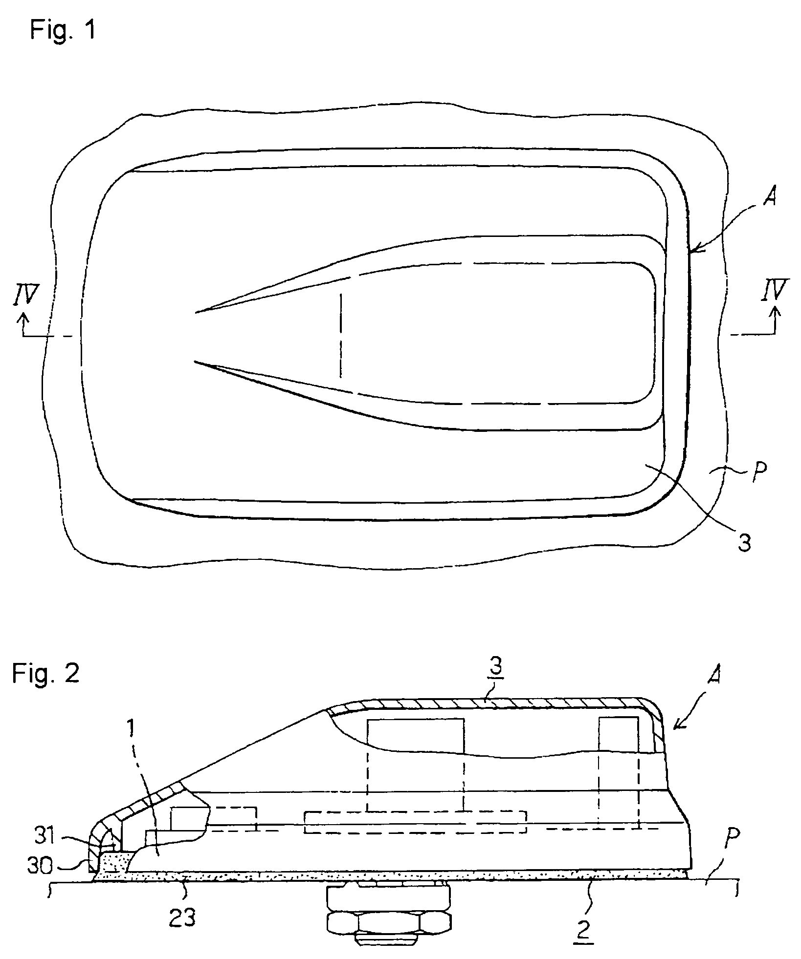
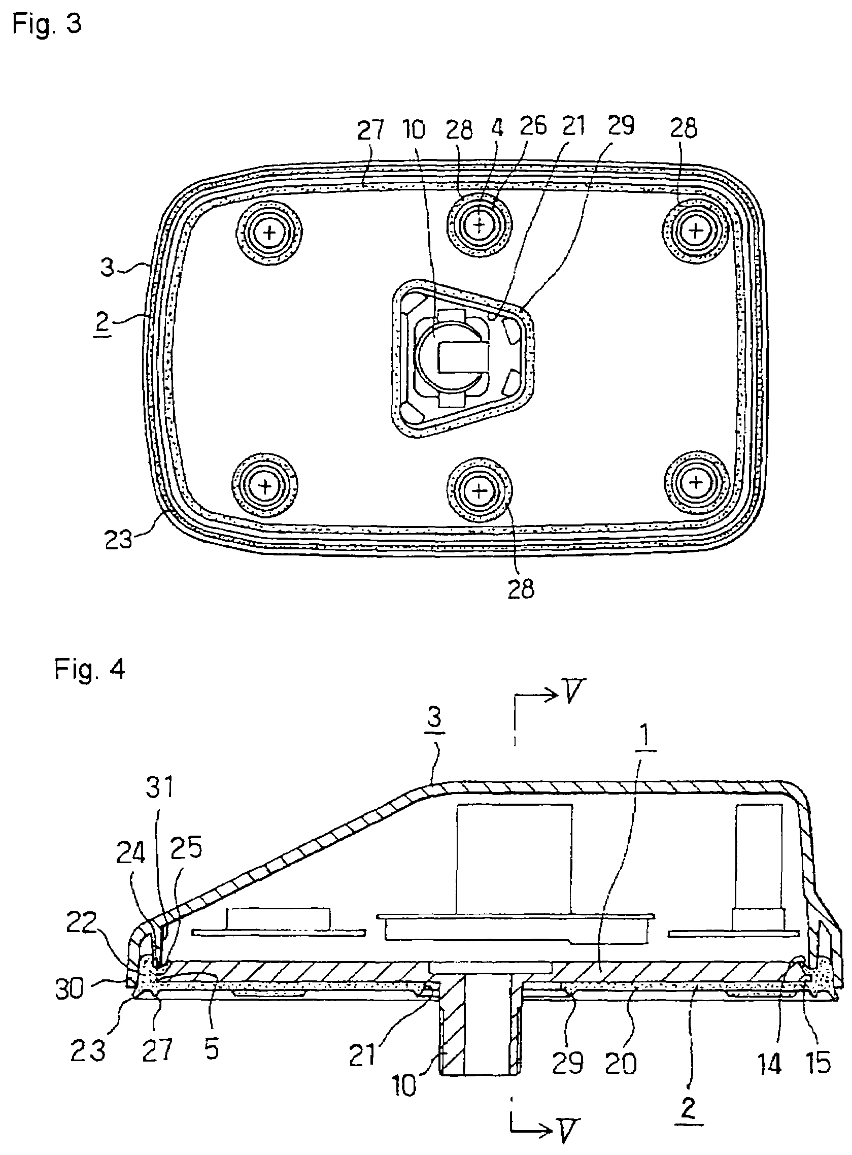
[0053]FIGS. 1 to 7 show a first embodiment of an antenna for automobiles, according to the invention. FIGS. 1 and 2 show a whole of the embodiment and FIGS. 3 to 7 show details thereof.

[0054]In FIGS. 1 and 2, A denotes an antenna, according to the invention, being fixed to an outside sheet panel P of a vehicle body, such as roof, A pillar, trunk lid, or the like.

[0055]The antenna A comprises, as shown in FIGS. 2 and 7, a base member 1 that supports an electrical equipment substrate including receiving or receiving / transmitting electrical parts, a base pad member 2 embracing a bottom and an outer periphery of the base member 1 to be made integral therewith, and a cover member 3 that fits onto the base pad member 2 to store the same in an outer profile of an opening thereof.

[0056]As shown in FIGS. 1 and 2, the cover member 3 is stationarily positioned in an appearance as formed such that a lower ...

second embodiment

[0076]FIGS. 8 to 12 show a second embodiment of the invention.

[0077]Also, in this embodiment, an antenna A comprises a base member 1 that supports an electrical equipment substrate including receiving or receiving / transmitting electrical parts, a pad member 2 embracing the base member 1 to be made integral therewith, and a cover member 3 that fits onto the pad member 2 to store the same in an outer profile of an opening thereof, the cover member 3 is stationarily positioned, as shown in FIG. 8, in an appearance as formed such that a lower portion thereof is close to a surface of the outside sheet panel P, and the pad member 2 is put in a state of being not visually recognized from above since it does not project outside from the cover member 3.

[0078]In the embodiment, the cover member 3 comprises an inner body 3a and an outer body 3b mounted thereon, and the pad member 2 has a feature in that a major portion thereof except a skirt 23 is fitted into the outer body 3b and the base mem...


PUM


Abstract

An automobile antenna capable of preserving a good outward appearance of an antenna shape intact while possessing favorable waterproof and dustproof qualities is provided.An antenna mounted on an outside sheet panel of an automobile and comprising a base member that supports electrical parts for reception and transmission, a cover member that receives the electrical parts for reception and transmission, and a pad member made of an elastic material, and wherein the pad member is fitted internally into the cover member while covering an underside and an outer peripheral portion of the base member.

Description

TECHNICAL FIELD[0001]The present invention relates to an automobile antenna.BACKGROUND ART[0002]Automobiles mount thereon various communications apparatuses such as radio, television, telephone, navigator, etc. to receive, transmit, or receive and transmit ground wave and satellite wave.[0003]Generally, such automobile antenna for reception, transmission, or reception and transmission comprises an antenna base, on which an electrical equipment substrate and bases of antenna elements are arranged, an antenna cover that covers the antenna base, and a sealing member (antenna pad) facing a vehicle body side, that is, an outer plate panel of an automobile.[0004]With conventional antennas of this kind, an antenna base is fitted inside an opening of an antenna base cover and an antenna base pad having a bottom wall is externally fitted and fixed to the antenna base cover.[0005]With such construction, however, the antenna base pad is mounted to an external shape of the antenna base, so that...

Claims


Application Information

Patent Timeline
Patent Type & Authority Patents(United States)
IPC IPC(8): H01Q1/32H01Q1/12H01Q1/22H01Q1/42H01Q23/00
CPCH01Q1/1214H01Q23/00H01Q1/42H01Q1/3275
Inventor TATENO, KOUICHI
Owner CLARION CO LTD
Why Eureka
Try Eureka