Apparatus and method for driving image display device using DMD

a technology of image display device and display device, which is applied in the direction of picture reproducers using projection devices, television systems, instruments, etc., can solve the problems of generating noise and inability to accurately know the timing of color filter change, so as to reduce the marginality of light mute regions, increase the use efficiency of light, and accurately detect the timing of color change

Inactive Publication Date: 2008-08-19
LG ELECTRONICS INC
View PDF6 Cites 3 Cited by
  • Summary
  • Abstract
  • Description
  • Claims
  • Application Information

AI Technical Summary

Benefits of technology

[0021]An object of the present invention is to provide an apparatus and method for driving an image display device using a DMD, in which a margin of a light mute region can be minimized by accurately detecting a timing of a color change during a rotation of a color wheel.
[0022]Also, another object of the present invention is to increase a use efficiency of light and improve a brightness of a projection-type image display.

Problems solved by technology

The reason is that it is impossible to accurately know the timing in the change of the color filters.
Also, the unused light is scattered and is changed into heat within the DLP system or projected on a screen, thus generating noise.

Method used


Image

  • Apparatus and method for driving image display device using DMD
  • Apparatus and method for driving image display device using DMD
  • Apparatus and method for driving image display device using DMD

Examples


Embodiment Construction

[0034]Reference will now be made in detail to the preferred embodiments of the present invention, examples of which are illustrated in the accompanying drawings. Wherever possible, the same reference numbers will be used throughout the drawings to refer to the same or like parts.

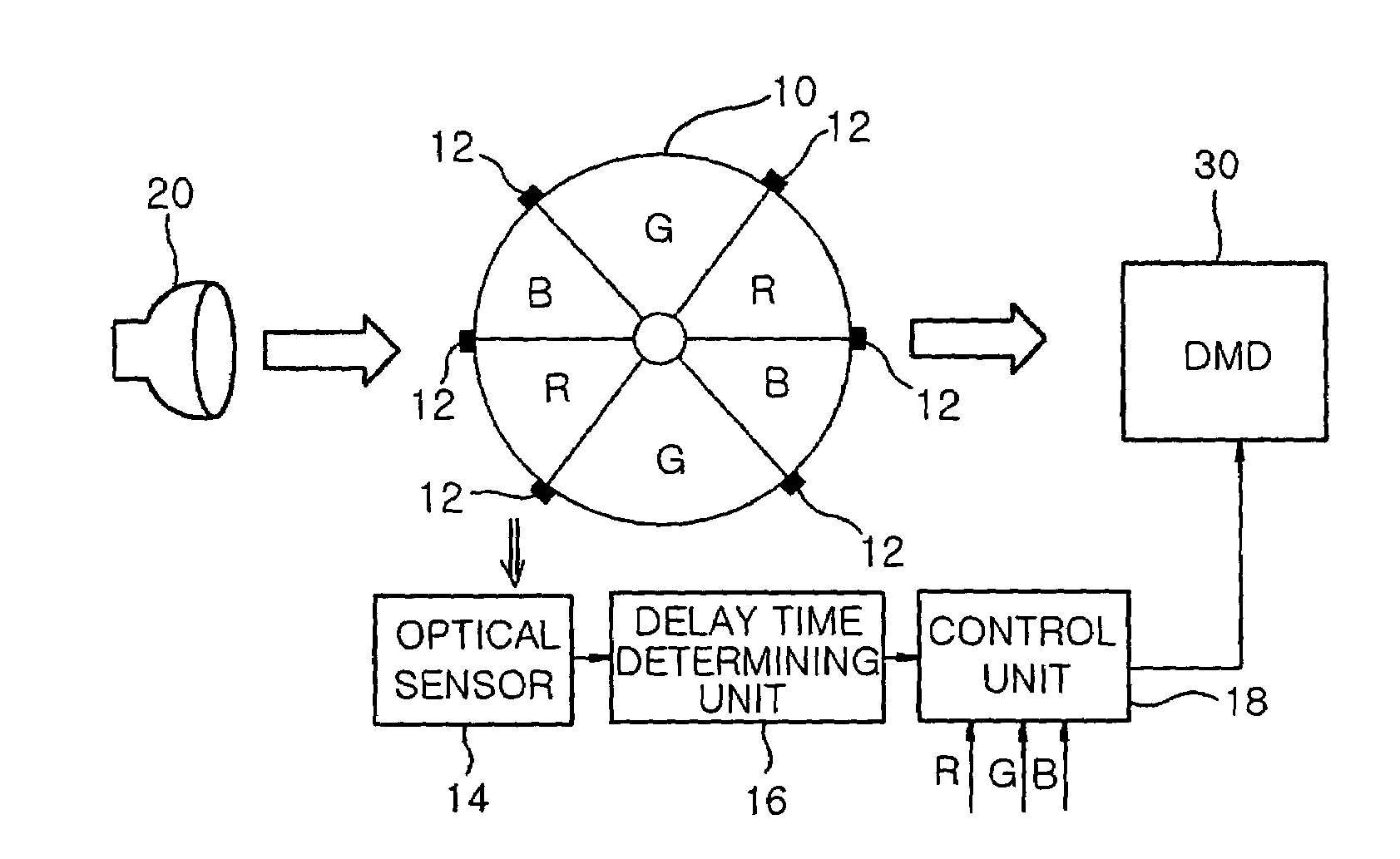
[0035]FIGS. 4 and 5 are views of an apparatus for driving an image display device using a DMD according to an embodiment of the present invention, and FIG. 6 illustrates a phase relationship between a change of the R, G and B color filters and R, G and B images actually displayed during the rotation of a color wheel in the apparatus for driving an image display device according to an embodiment of the present invention.

[0036]Referring to FIGS. 4 to 6, the apparatus for driving the image display device using the DMD includes a color wheel 10, an optical sensor 14, a delay time determining unit 16, and a control unit 18. The color wheel 10 includes two RGB color filters and six index marks 12 disposed at porti...


PUM


Abstract

An apparatus and method for driving an image display device using a DMD are provided. The apparatus includes a color wheel, an optical sensor, a delay time determining unit, and a control unit. The color wheel includes a plurality of color filters and index marks formed at positions corresponding to boundary lines between the color filters, and the optical sensor detects the index marks during rotation of the color wheel and outputs detection signals. The delay time determining unit determines a delay time corresponding to a minimum margin required in a conversion of a color image signal according to the detection signal inputted from the optical sensor, and the control unit controls a DMD based on the detection signals and the delay time.

Description

BACKGROUND OF THE INVENTION[0001]1. Field of the Invention[0002]The present invention relates to an apparatus and method for driving an image display device using a DMD, and more particularly, to an apparatus and method for driving an image display device using a DMD, in which a margin of a light mute region at a color change can be minimized by correctly detecting a timing in a change of a color filter during rotation of a color wheel employed in a projection-type image display device using a DMD.[0003]2. Description of the Related Art[0004]Recently, with the advance of information industries, image display devices capable of displaying a large-sized image are in great demand. One of them is a projection-type image display device. A digital light processing (DLP) projector and a DLP projection TV using a digital micromirror device (DMD) are spotlighted.[0005]FIGS. 1 and 2 are views of a color wheel used in a related art DLP projector or DLP projection TV.[0006]Referring to FIGS. 1 ...

Claims


Application Information

Patent Timeline
Patent Type & Authority Patents(United States)
IPC IPC(8): H04N9/12G03B21/14H04N9/31
CPCH04N9/3114H04N9/3197H04N9/312E04C5/166
Inventor KIM, SUNG MIN
Owner LG ELECTRONICS INC
Why Eureka
Try Eureka