Method for determining the sound velocity in a basic material, particularly for measuring the thickness of a wall

Inactive Publication Date: 2008-08-26
AGFA NDT
View PDF6 Cites 52 Cited by
  • Summary
  • Abstract
  • Description
  • Claims
  • Application Information

AI Technical Summary

Benefits of technology

[0008]The achievement of the invention is that it relies on the observation that in determining the shortest travel time Ttot of the ultrasound pulse and in optimizing all of the possible sound travel paths leading to the sound travel path that supplies the shortest total travel time as a function of Cb, one obtains precise information about the sound

Problems solved by technology

However, a probe the precursor body of which has a short sound travel distance suffers from the disadvantage that but little material of the precursor body is

Method used


Image

  • Method for determining the sound velocity in a basic material, particularly for measuring the thickness of a wall
  • Method for determining the sound velocity in a basic material, particularly for measuring the thickness of a wall
  • Method for determining the sound velocity in a basic material, particularly for measuring the thickness of a wall

Examples


Embodiment Construction

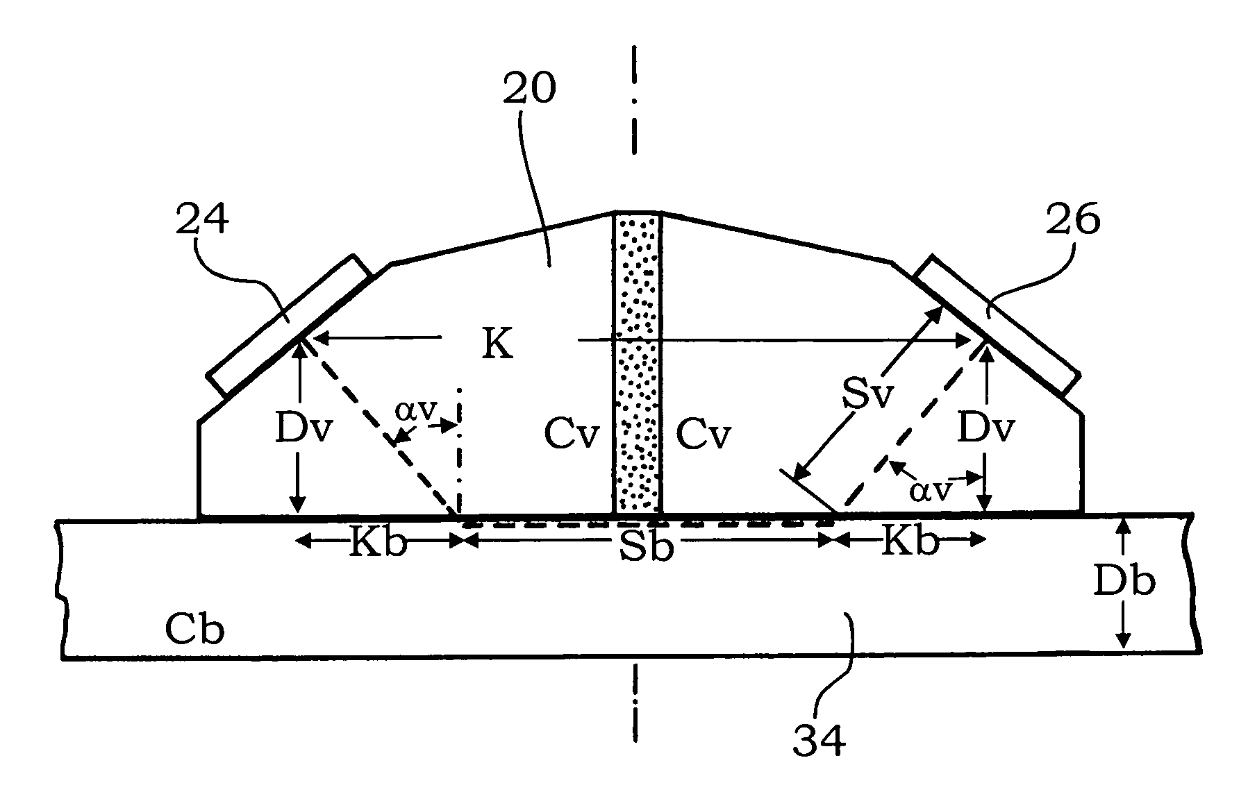
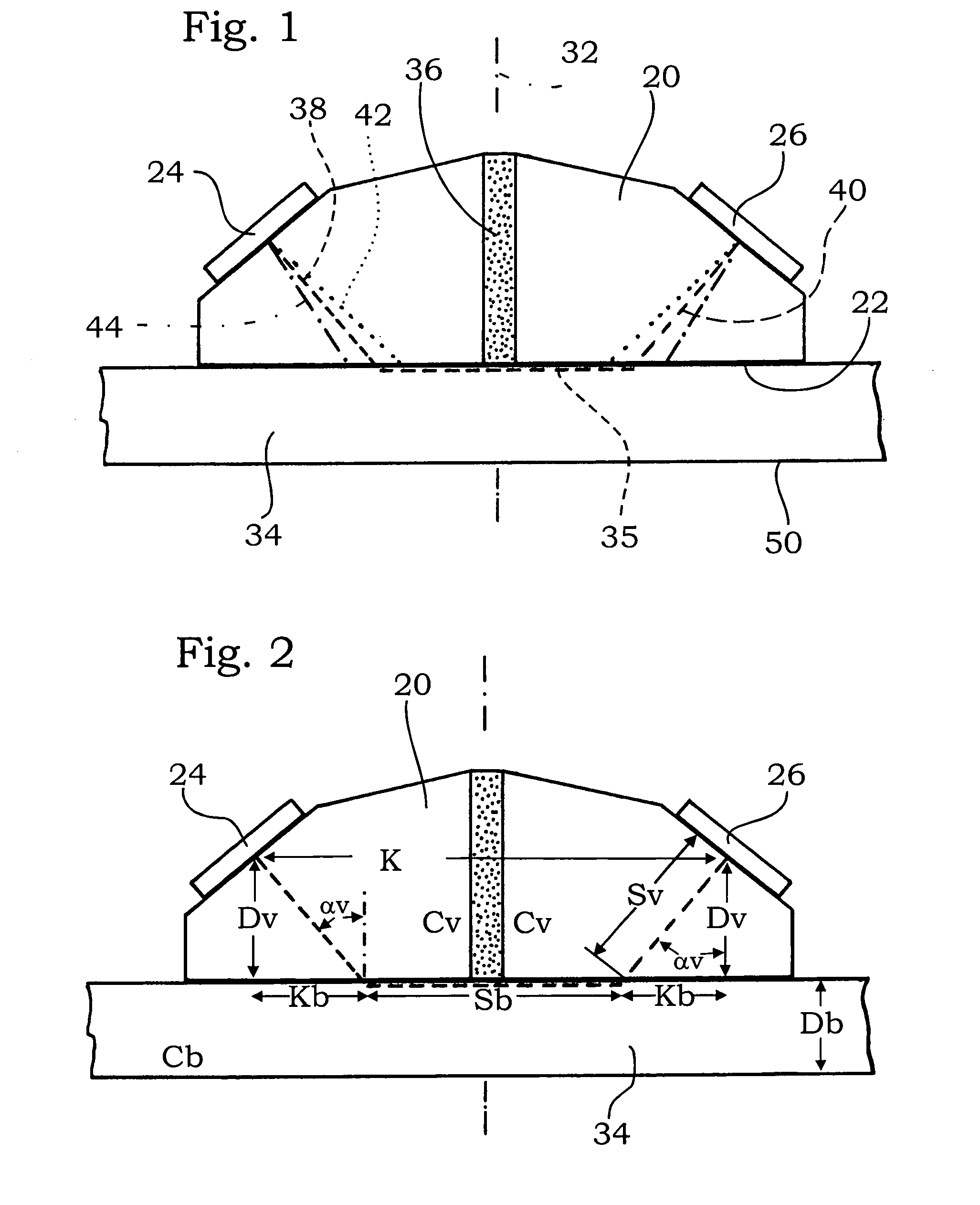
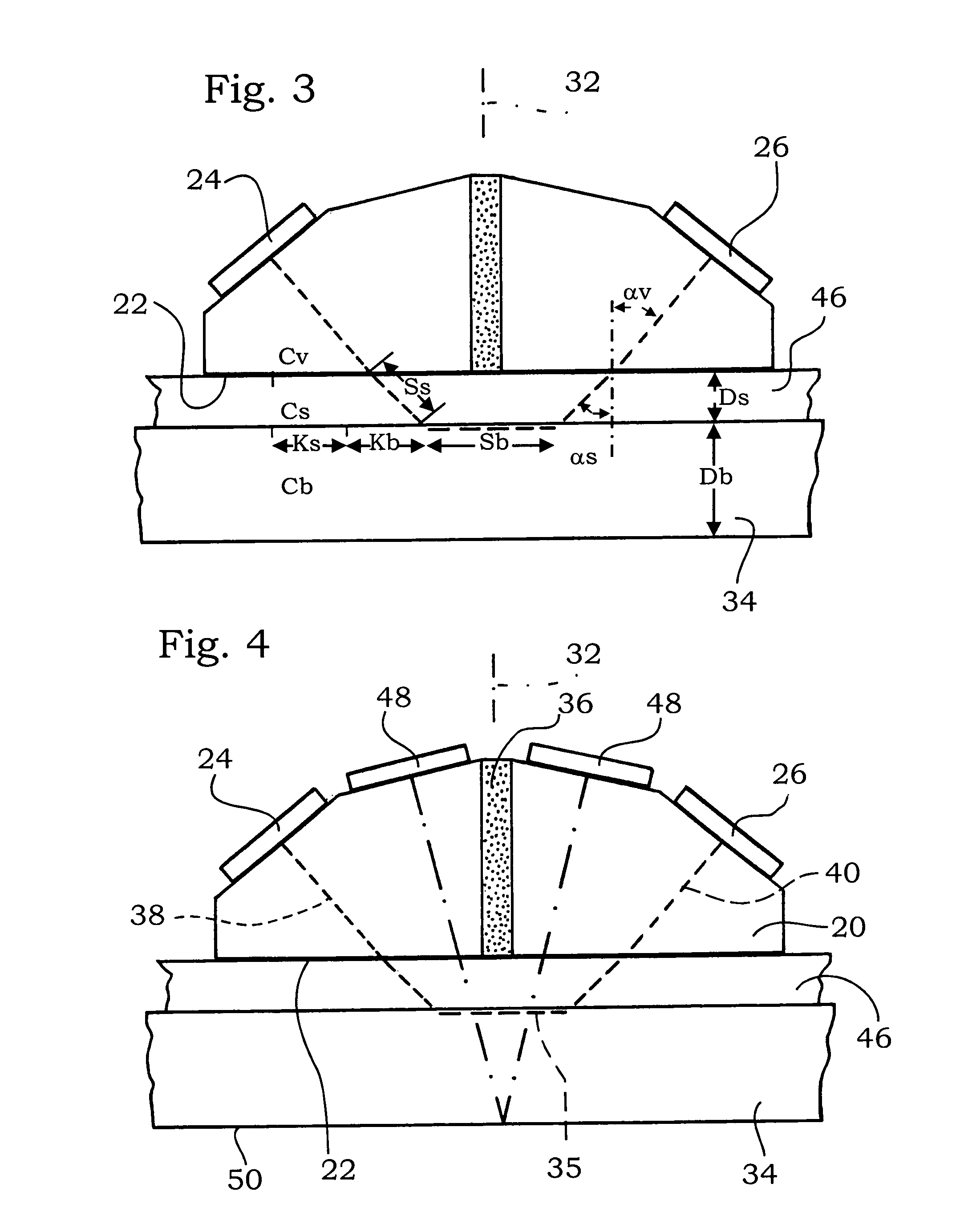
[0015]The probe shown in FIG. 1 has a specially shaped, substantially prismatic precursor body 20. It has a level coupling surface 22, which is also referred to as the active surface, and, on the opposite side thereof, bevels on which a transmit crystal 24 and a receive crystal 26 are respectively retained, more specifically cemented. The two crystals 24, 26 are built according to the same principle. They are disposed at an incline toward each other and also relative to the coupling surface 22. This arrangement will be discussed in further detail herein after.

[0016]A perpendicular bisector, meaning a line that perpendicularly bisects said crystal contact surface with the precursor body 20, is inclined at a certain angle relative to the coupling surface 22, said angle being (90°−αv) and being the same for the two crystals 24, 26. Further, the respective perpendicular bisectors lie in the same plane, namely in the plane of FIG. 1.

[0017]This may also be put another way: the two crystal...


PUM


Abstract

Disclosed is a method for determining the sound velocity (Cb) in a basic material, in which an ultrasonic probe having a transmitting probe, a receiver transducer, and a forward member is used. The forward member is provided with a coupling surface that couples the probe to the basic material, and has a sound velocity (Cv). The transmitting probe and the receiver transducer are aligned in an oblique manner from each other and from the coupling surface such that a main transmission direction of the transmitting probe and a main receiving direction of the receiver transducer intersect below the coupling surface. The centers of the transmitting probe and the receiver transducer are located at a distance K from each other and are located at a distance Dv from the coupling surface. According to the inventive method, the transmitting probe generates an ultrasonic pulse which runs through the forward member into the basic material, where the ultrasonic pulse creates a creeping wave, a portion of which arrives at the receiver transducer. The shortest sound traveling time (Ttot) is measured and the sound velocity (Cb) within the basic material is determined via the path between the transmitting probe and the receiver transducer, which supplies the shortest total traveling time (Ttot).

Description

TECHNICAL FIELD OF INVENTION[0001]The invention relates to a method for determining the sound velocity Cb in a base material, using an ultrasonic probe comprising a transmit crystal, a receive crystal and a precursor body, said precursor body a) having a coupling surface by which the probe is couplable to the base material, b) receiving the receive crystal and the transmit crystal and c) having a sound velocity Cv, the transmit crystal and the receive crystal being oriented to be inclined towards each other and each towards the coupling surface so that a main transmission direction of the transmit crystal and a main receiving direction of the receive crystal intersect below the coupling surface, transmit crystal and receive crystal being spaced apart at a center to center distance K, the transmit crystal being spaced at a center to center distance Ds from the coupling surface and the receive crystal at a distance De from the coupling surface, by which method an ultrasonic pulse is g...

Claims


Application Information

Patent Timeline
IPC IPC(8): G01N29/00G01B17/02G01N29/04G01N29/07G01N29/44
CPCG01B17/025G01N29/041G01N29/07G01N29/4472G01N2291/057G01N2291/02854G01N2291/0421
Inventor RENZEL, PETER
Owner AGFA NDT
Why Eureka
Try Eureka