Internal combustion engine

a combustion engine and internal combustion technology, applied in the direction of liquid fuel engines, machines/engines, rotary piston liquid engines, etc., can solve the problems of low efficiency of these engines, and achieve the effects of reducing the size of the engine, facilitating the operation of inventive internal combustion engines, and enhancing clean and efficient combustion

Active Publication Date: 2008-08-26
REISSER HEINZ GUSTAV A
View PDF17 Cites 23 Cited by
  • Summary
  • Abstract
  • Description
  • Claims
  • Application Information

AI Technical Summary

Benefits of technology

[0005]In contrast to conventional combustion engines, the inventive combustion engine comprises a combustion chamber which is not only delimited by a wall of the engine housing and a first piston head of a first piston, but also by a second piston head of a second piston. The wall of the engine housing defines at least a section of a torus in which the pistons are guided, so that the pistons travel along a curved path. When the combustion gas is ignited in a combustion chamber that is delimited as described, the two pistons are driven in opposite directions, i.e. forced apart, and transmit their motion to the crankshafts via their connecting rods. The gases expanding in the combustion chamber thereby drive not only one, but two pistons to substantially increase the efficiency of the engine. This reduces fuel consumption and improves emission values.
[0017]When the first crankshaft and the second crankshaft rotate in a same direction, the coupling to a flywheel is very easy, since it can be directly interposed between the two crankshafts.

Problems solved by technology

The efficiency of these engines is, however, very low.

Method used


Image

  • Internal combustion engine
  • Internal combustion engine
  • Internal combustion engine

Examples


Embodiment Construction

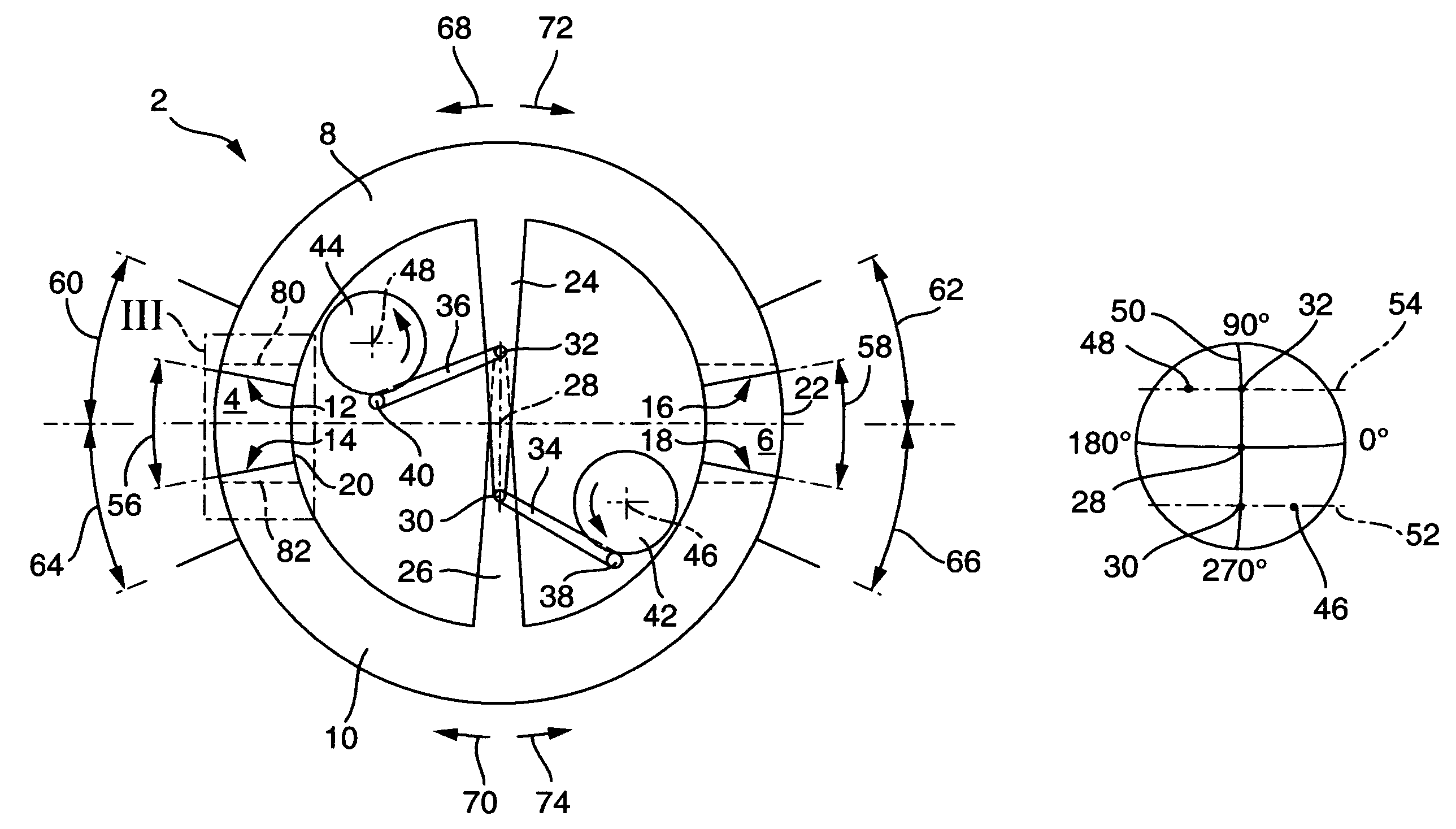
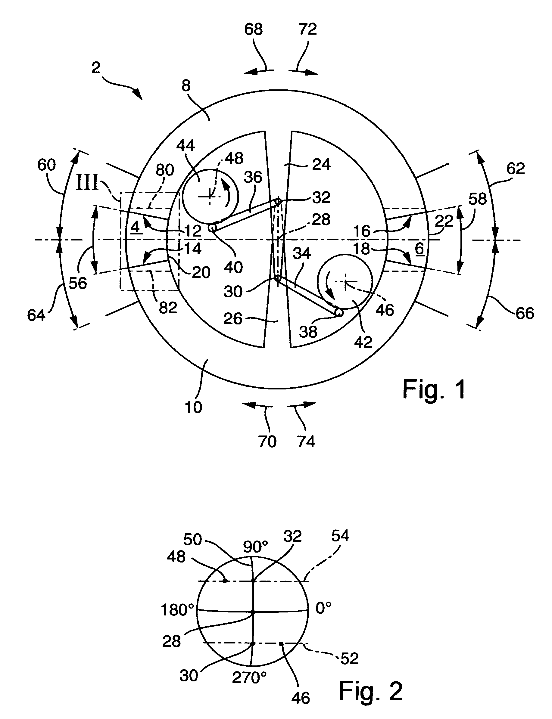
[0023]FIG. 1 shows the main parts of an inventive internal combustion engine 2. This engine comprises two combustion chambers, a first combustion chamber 4 and a second combustion chamber 6. A first piston 8 and a second piston 10 delimit each combustion chamber. The pistons 8 and 10 have a torus shape and each comprises two piston heads. The first piston 8 comprises a first piston head 12 and the second piston 10 comprises a second piston head 14, which is arranged opposite to the first piston head 12.

[0024]At its other end, the first piston 8 comprises a third piston head 16, which is arranged opposite to a fourth piston head 18, provided on the second piston 10.

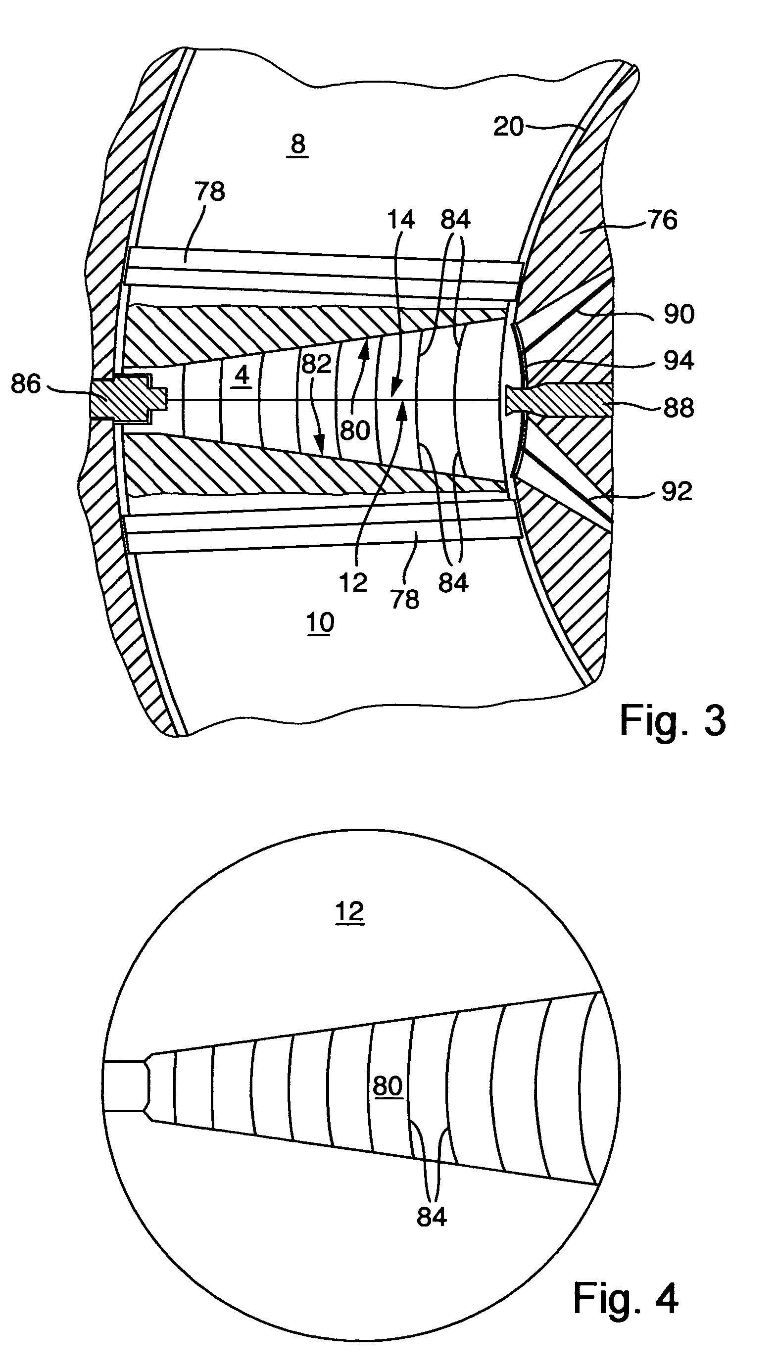
[0025]The first combustion chamber 4 is not only delimited by the piston heads 12 and 14, but also by a first wall 20, which is provided by an engine housing (shown in greater detail in FIG. 3). The second combustion chamber 6 is accordingly delimited by a second wall 22. The walls 20 and 22 have the shape of a section of ...


PUM


Abstract

An internal-combustion engine comprises an engine housing having a first wall delimiting a first combustion chamber, a first piston also delimiting said first combustion chamber and with a first piston head, a first crankshaft, a second piston also delimiting said first combustion chamber and with a second piston head, a second crankshaft, and a second connecting rod connected between said second piston and said second crankshaft, said first wail defining at least a section of a torus, said pistons being guided along a curved path defined by said section of a torus.

Description

BACKGROUND OF THE INVENTION[0001]The invention concerns an internal-combustion engine with an engine housing comprising a first wall delimiting a first combustion chamber, with a first piston also delimiting said first combustion chamber by means of a first piston head and with a first crankshaft.[0002]Engines of this type have been known for more than a hundred years and are used as stationary drives as well as for vehicles. In these engines, the walls delimiting the combustion chambers are of cylindrical shape and closed on one side with a cylinder head. On the other side, a piston is moveably guided in the cylinder to transfer the driving force to a crankshaft via a connecting rod as the combustion gases expand. Combustion engines operating according to this principle may function in two cycles or four cycles, such as Otto and diesel engines. The efficiency of these engines is, however, very low.[0003]It is the underlying purpose of the invention to provide a combustion engine ha...

Claims


Application Information

Patent Timeline
Patent Type & Authority Patents(United States)
IPC IPC(8): F02B53/00
CPCF01C9/002F02B53/02Y02T10/17Y02T10/12
Inventor REISSER, HEINZ-GUSTAV A.
Owner REISSER HEINZ GUSTAV A
Why Eureka
Try Eureka