
One-way damper and electronic devices using the one-way damper

a one-way damper and electronic device technology, applied in the field of one-way dampers, can solve the problem that the damping torque cannot be obtained in a conventional one-way damper, and achieve the effects of preventing damage and breakage of the rotor, and reducing the risk of damage to the inputting part and the monitor par

Inactive Publication Date: 2008-08-26
NIFCO INC
View PDF14 Cites 11 Cited by
  • Summary
  • Abstract
  • Description
  • Claims
  • Application Information

AI Technical Summary

Benefits of technology

The present invention provides a one-way damper that can control the movement of an inputting part or a monitor part of an electronic device. The damper includes a cylinder shaped housing, viscous fluid, a center part, a rotor, a holding part, a valve body, and a seal member. The rotor is made of a synthetic resin with elasticity, and the valve body is positioned in a groove. The distribution path of the damper is structured so as to open and close at the free edge part, and a rotation restriction part restricts rotation of the rotor. The system using the damper includes an electronic device with an inputting part or a monitor part attached to it, and the damper can control the movement of the inputting part or the monitor part. The damper prevents damage and breakage of the rotor and maintains a certain accuracy of the damping torque. The one-way damper is also suitable for controlling the movement of the inputting part or the monitor part when the electronic device is attached to a force applying member.

Problems solved by technology

Accordingly, large damping torque cannot be obtained in a conventional one-way damper.

Method used


Image

  • One-way damper and electronic devices using the one-way damper
  • One-way damper and electronic devices using the one-way damper
  • One-way damper and electronic devices using the one-way damper

Examples


Embodiment Construction

[0036]Hereunder, embodiments of the present invention will be explained in detail with reference to the accompanying drawings.

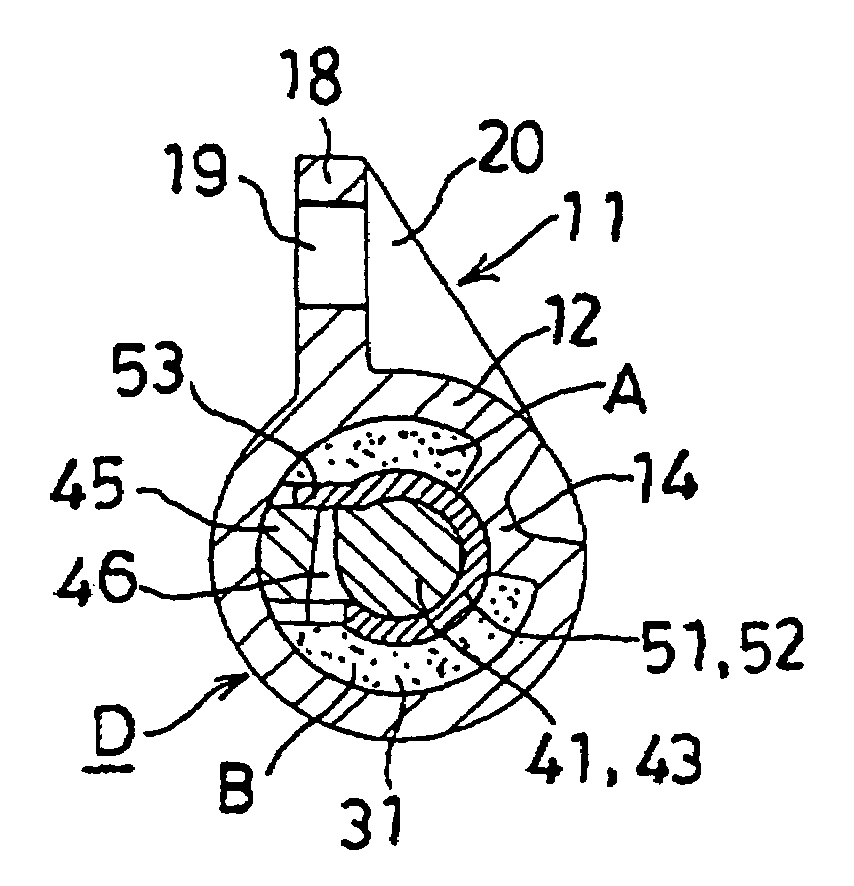
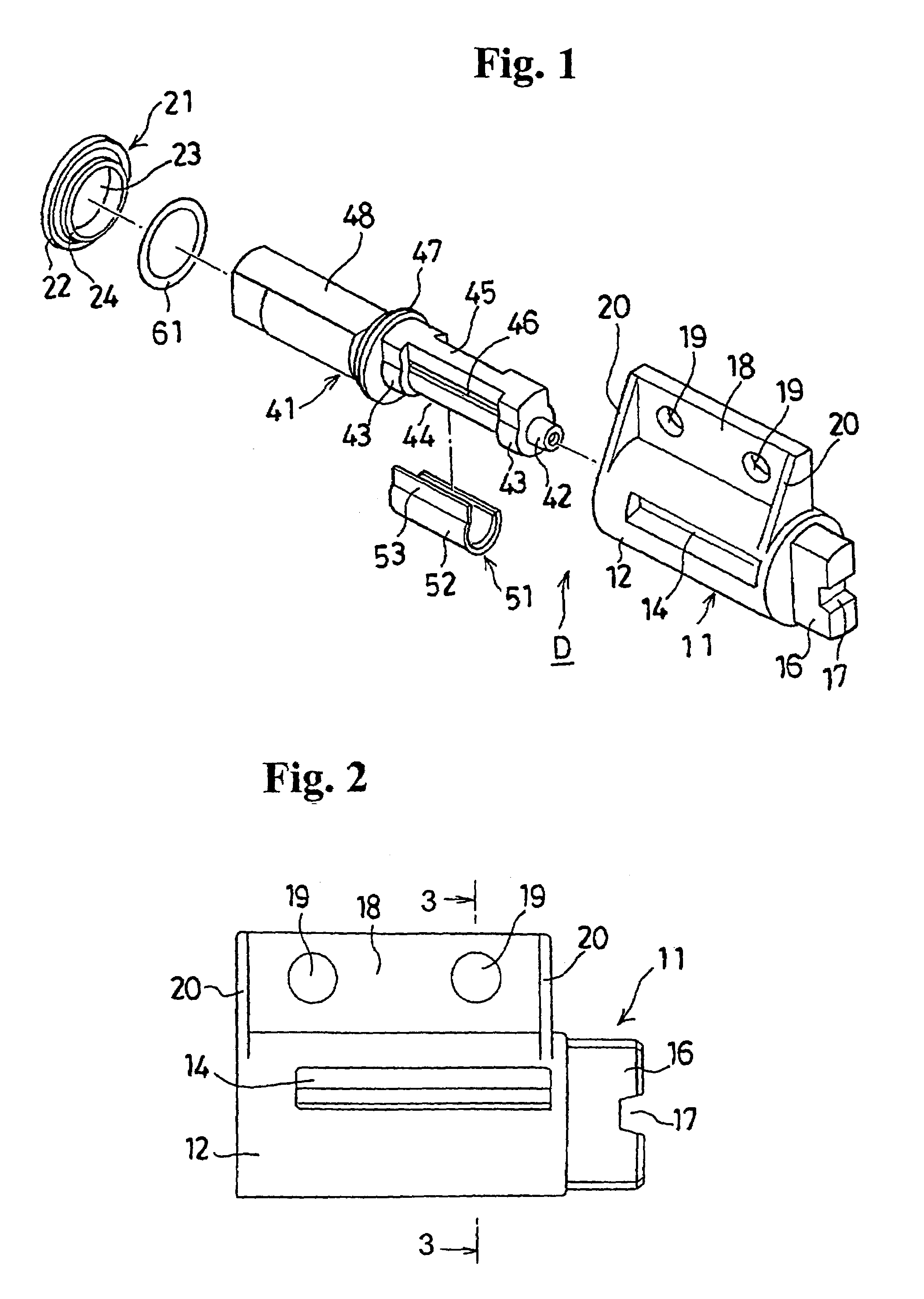
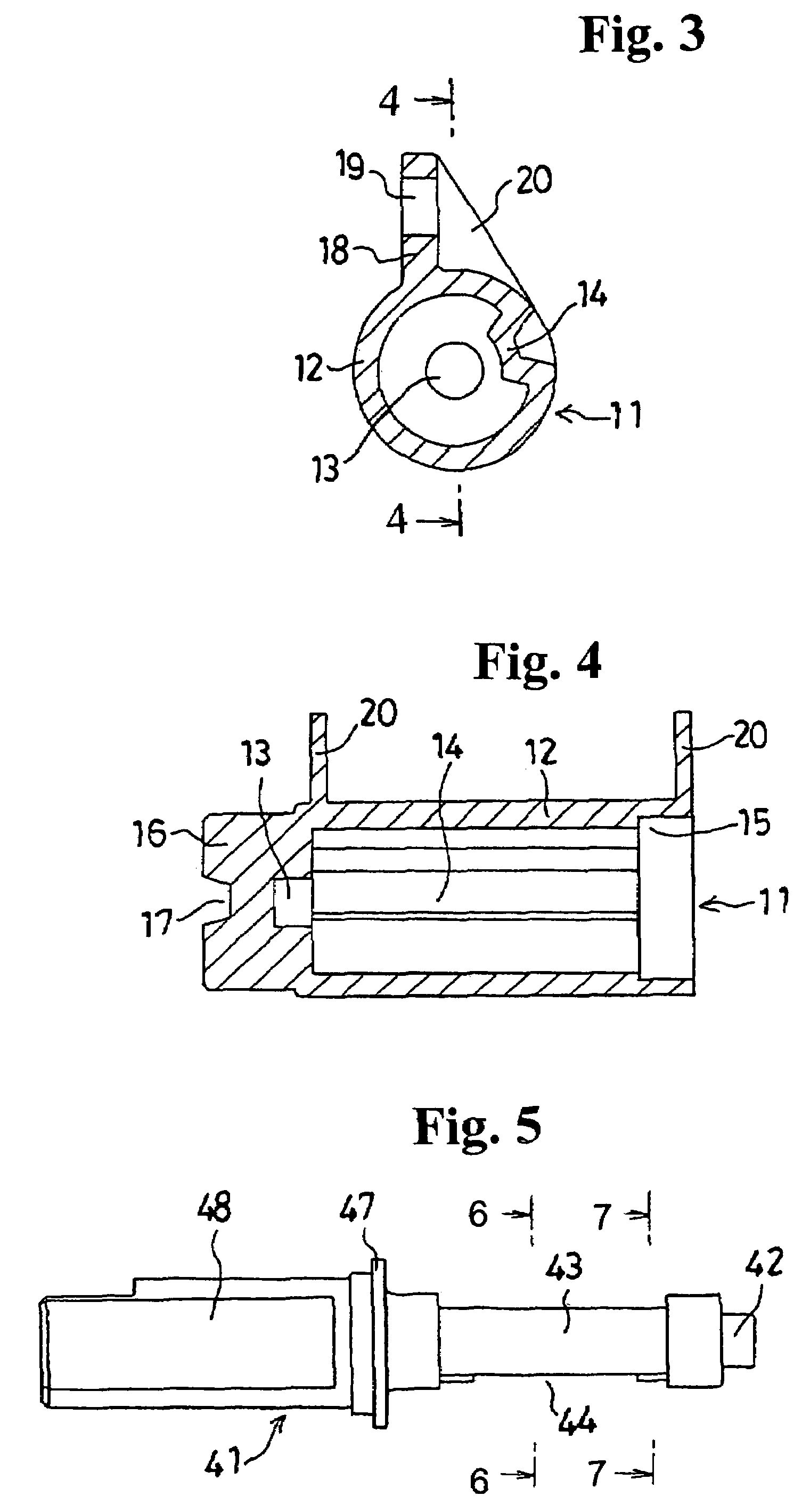
[0037]FIG. 1 shows a one-way damper in a disassembled state according-to an embodiment of the present invention. The one-way damper is made of a rigid material, such as a synthetic resin. For example, the case 11 is made of polycarbonate, which is a synthetic resin having rigidity. Cap 21, which seals the opening end of the case 11, is also made-of polycarbonate. Silicone oil (not shown in figures), which is a viscous fluid, is housed in the case 11, which is sealed by the cap 21. FIG. 1 also shows, a synthetic resin rotatably housed in the case 11 and which has operation axis part 48, which extends through a hole 23 of the cap 21 to outside. A rotor 41 is made of a synthetic resin, such as polyester, and a valve 51, also made of polyester, is attached to the rotor 41. O-ring 61, which is made of a self-lubricated silicone rubber, serves as a seal member to p...


PUM


Abstract

A one-way damper includes a cylindrical housing, a viscous fluid contained within the housing, a rotor rotatably disposed in the housing, and a valve body. The rotor has a center part for forming a rotational center, and a control wall extending radially outwardly from the center part for dividing an inside of the housing. The control wall has a distribution path. The valve body has a holding part for holding the center part, and a free edge part extending from one side of the holding part for opening-and closing the distribution path. A seal member prevents the viscous fluid from leaking between the housing and the rotor.

Description

BACKGROUND OF THE INVENTION AND RELATED ART STATEMENT[0001]The present invention relates to a one-way damper, and in particular to a one-way damper that controls the rotation of a body in one direction, and electronic devices using this one-way damper.[0002]A conventional one-way damper includes a cylinder shaped housing, viscous fluid within this housing, a center part which is a center of the rotation, a rotor which divides the inside of the housing by standing to the diameter direction from this center part and which has a control wall which forms a connecting path with respect to the housing, and in which the center part and the control wall are rotatably housed in the housing. The conventional one-way damper also includes a control valve, in which one side near the control wall is the rotation center, and the other side contacts the inner surface of the housing, and rotates with the rotor, and a seal member which prevents viscous fluid from leaking between the housing and the r...

Claims


Application Information

Patent Timeline
Patent Type & Authority Patents(United States)
IPC IPC(8): F16D57/02E05F3/20F16F9/14
CPCF16F9/145Y10T16/2771G11B33/08
Inventor ARAKI, MINORUTANAKA, MASAMI
Owner NIFCO INC
Learn More