Frequency regulating method for tuning fork type vibrator and tuning fork type vibrator frequency-regulated by the method

a technology of frequency regulation and tuning fork type, which is applied in the direction of piezoelectric/electrostrictive/magnetostrictive devices, oscillator generators, piezoelectric/electrostrictive/magnetostrictive machines, etc., to achieve the effect of improving the production efficiency of resonators and faster frequency adjustment procedures

Active Publication Date: 2008-08-26
DAISHINKU CORP
View PDF14 Cites 2 Cited by
  • Summary
  • Abstract
  • Description
  • Claims
  • Application Information

AI Technical Summary

Benefits of technology

[0009]According to this invention, the frequency adjustment is performed by forming the metal film on a tip portion including at least one surface of side surfaces or tip surfaces of each leg portion, and removing the metal film formed on at least one surface of the side surfaces or the tip surfaces. Thus, it is possible to use more effectively a region of the metal film for adjustment, which is limited due to miniaturization of a piezoelectric element. Further, since an effective region can be secured on the metal film formed on the major surfaces, the metal film can be additionally removed with another fine adjustment technique (e.g., milling, partial deposition, etc.) in a subsequent step in a stable manner. Specifically, in the case of milling, after rough adjustment is performed by removing only the side surface using a laser, the entire metal film remaining on the major surface can be used as a weight for fine adjustment. Therefore, stable fine adjustment can be performed by removing the metal film. In the case of partial deposition, after rough adjustment is performed by removing only the side surface using laser, the entire metal film remaining on the major surface can be used as an underlying metal for fine adjustment. Therefore, stable fine adjustment can be performed by adding metal film.
[0032]According to the present invention, it is possible to provide a tuning fork resonator capable of emitting a transmission signal having a frequency equal to a target frequency. Further, a frequency adjustment procedure can be performed more quickly and the production efficiency of a resonator can be improved, resulting in a low-cost tuning fork resonator.

Problems solved by technology

Thus, it is possible to use more effectively a region of the metal film for adjustment, which is limited due to miniaturization of a piezoelectric element.

Method used


Image

  • Frequency regulating method for tuning fork type vibrator and tuning fork type vibrator frequency-regulated by the method
  • Frequency regulating method for tuning fork type vibrator and tuning fork type vibrator frequency-regulated by the method
  • Frequency regulating method for tuning fork type vibrator and tuning fork type vibrator frequency-regulated by the method

Examples


Embodiment Construction

[0047]Hereinafter, embodiments of the present invention will be described with reference to the accompanying drawings. A tuning fork resonator will be described before explaining a frequency adjusting method of the embodiments. Hereinafter, embodiments of the present invention will be described with reference to the accompanying drawings. It should be noted that, in the following embodiments, the present invention is applied to a crystal resonator as a tuning fork resonator, and the present invention is applied to a tuning fork crystal element as a piezoelectric element. However, the present invention is not limited to this. The crystal resonator and the tuning fork crystal element are preferable illustrative embodiments.

Description of Crystal Resonator (Tuning Fork Resonator as Described Herein)

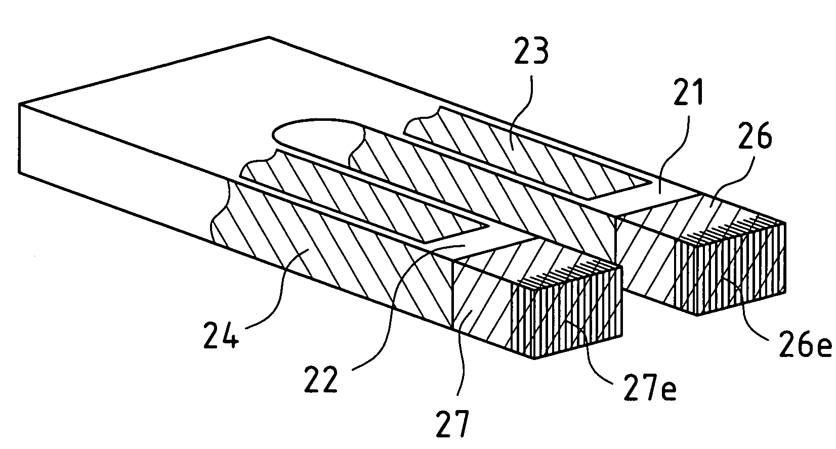
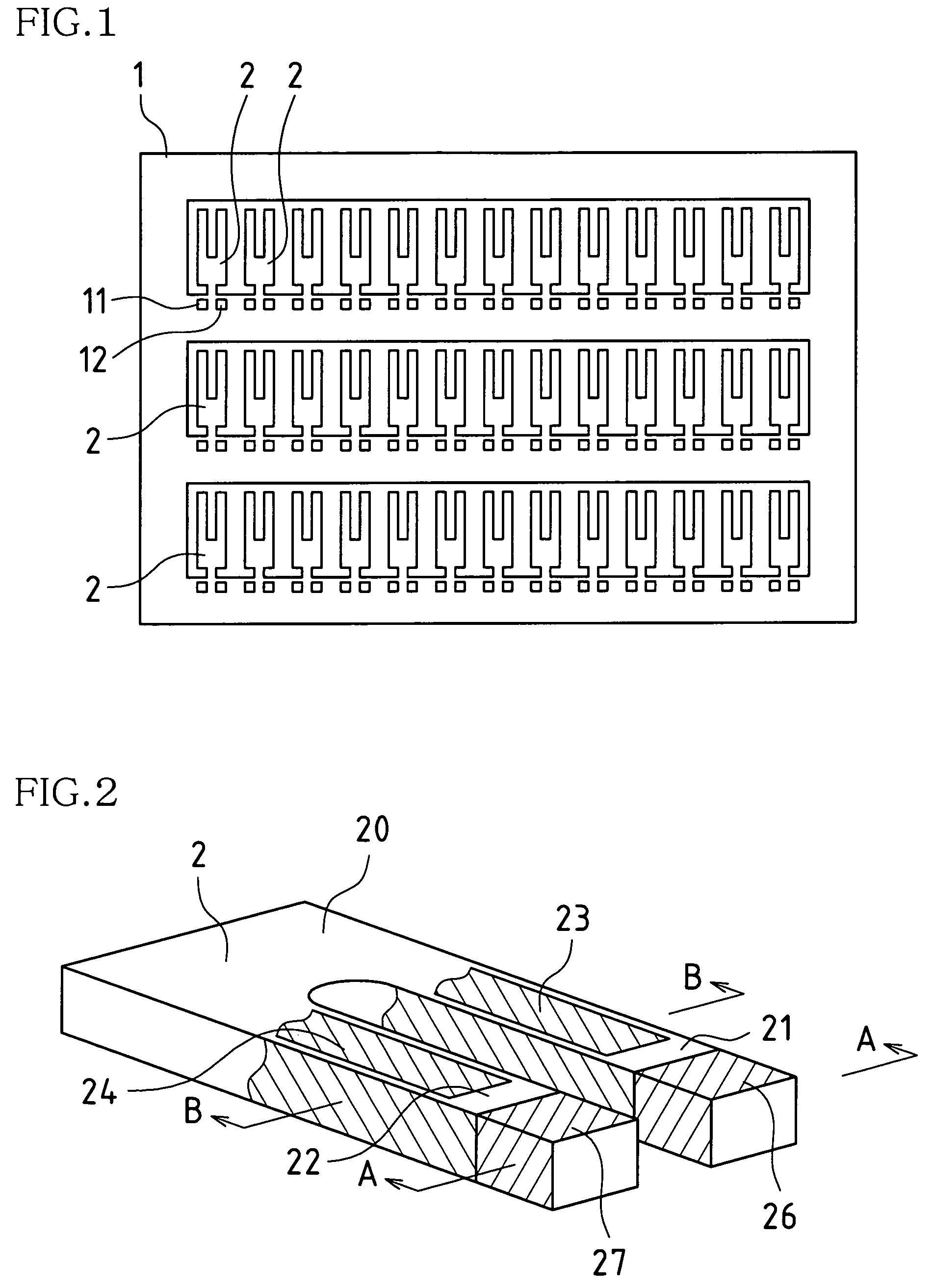
[0048]FIG. 1 is a plan view showing a crystal wafer 1 according to the embodiment described herein. FIG. 2 is a diagram schematically showing one tuning fork crystal element 2 (hereinafter r...


PUM


Abstract

A piezoelectric element of a tuning fork resonator comprises a base portion and a plurality of leg portions. Drive electrodes are formed on top and bottom major surfaces and both side surfaces of each leg portion. The drive electrodes have polarities different between on the top and bottom major surfaces and the both side surfaces. The drive electrodes on the side surfaces are connected to each other. Further, metal film for frequency adjustment is formed on a tip portion of each leg portion of the piezoelectric element. The frequency adjustment is performed by removing the metal film formed on at least one surface of side surfaces and a tip surface of the tip portion by beam irradiation.

Description

TECHNICAL FIELD[0001]The present invention relates to a method for adjusting a frequency of a tuning fork resonator and a tuning fork resonator with a frequency adjusted by the method.BACKGROUND ART[0002]A production process of a tuning fork resonator (hereinafter referred to as a resonator) includes a step of adjusting an oscillation frequency. As a conventional resonator frequency adjusting method for this step, a method for adjusting the frequency of a resonator is disclosed in, for example, JP 2002-164759A.[0003]A resonator disclosed in JP 2002-164759A is provided with a piezoelectric element (hereinafter referred to as an element) there within. The element includes a base portion and two leg portions. In addition, a metal film is provided on the top and bottom major surfaces of the two leg portions so as to adjust frequency.[0004]In the resonator frequency adjusting method of JP2002-164759A, an oscillation frequency is adjusted by removing a portion of the top and bottom major ...

Claims


Application Information

Patent Timeline
Patent Type & Authority Patents(United States)
IPC IPC(8): H03H9/21H03H3/02
CPCH03H3/02H03H9/21H03H2003/0492H03H2003/026
Inventor SATOH, SYUNSUKESHIRAI, TAKASHI
Owner DAISHINKU CORP
Why Eureka
Try Eureka