Visible and infrared light photographing lens system

a technology of infrared light and photographing lens, which is applied in the field of visible and infrared light photographing lens system, can solve the problems of inability to compensate for any difference in photographing distance between visible light and visible light, disadvantageous uniform distance, etc., and achieves the effect of avoiding causing the photographer much trouble, reducing costs, and increasing the size of the system and cos

Active Publication Date: 2008-08-26
FUJIFILM CORP
View PDF14 Cites 46 Cited by
  • Summary
  • Abstract
  • Description
  • Claims
  • Application Information

AI Technical Summary

Benefits of technology

[0011]On the other hand, if an object light from an object to be photographed is divided into an object light for a visible light and an object light for an infrared light using a mirror or a prism so that the object lights obtained are allowed to enter photographing lens of a visible and infrared light cameras, respectively, as described above, the photographing lenses of the respective cameras can be used to individually adjust the focus. It is thus possible to focus on the object at the same position. However, if the two cameras are used, they must be simultaneously operated in carrying out focusing, zooming, or the like so that their photographing distances or angles of view are equal to each other. This requires much time and effort. Further, the size of the whole apparatus must be increased and the two photographing lenses are required for the visible and infrared light cameras. This increases costs. Moreover, if the mirror or prism is placed in front of the photographing lens, it must be larger than a front lens of the photographing lens. Consequently, a relatively large mirror or prism must be used in the apparatus, thus increasing the size of the apparatus and costs.
[0012]In view of these circumstances, it is an object of the present invention to provide a visible and infrared light photographing lens system which enables the same object to be easily photographed simultaneously with a visible and infrared lights without requiring much time or effort and which can suppress an increase in the size of the apparatus and in costs.
[0021]According to the present invention, the compensation lens and others are used to make the object distance to the object at which the object can be focused on with visible light photographing equal to the object distance to the object at which the object can be focused on with infrared light photographing. Consequently, it is possible to focus on and simultaneously photograph the same object at the same object distance for the visible and infrared lights. Further, the compensation lens and others are automatically controlled on the basis of, for example, the position of the focus lens. This avoids causing the photographer much trouble.
[0022]Further, the light dividing device, which divides the object light into the visible light object light and the infrared light object light, is placed behind the focus lens, used for both visible light photographing and infrared light photographing. This prevents an increase in the size of the light dividing device and thus an increase in the size of the system and in costs. The costs can also be reduced by using the focus lens for both visible light photographing and infrared light photographing.

Problems solved by technology

However, Japanese patent application Publication No. 2003-69865 does not assume simultaneous photographing with visible and infrared lights.
Accordingly, a problem may occur if visible light photographing and infrared light photographing are simultaneously carried out.
Thus, when the focus and zoom lens are set at predetermined positions and even if the photographing distance for the visible light is equal to the photographing distance for the infrared light, the photographing distances may disadvantageously become unequal if the focus or zoom lens is moved from its predetermined position.
Further, Japanese patent application Publication No. 2003-69865 has no devices that individually adjust the focus position for the visible and infrared lights.
Consequently, it cannot compensate for any difference in photographing distance between the visible light and the infrared light.
This requires much time and effort.
This increases costs.
Consequently, a relatively large mirror or prism must be used in the apparatus, thus increasing the size of the apparatus and costs.

Method used


Image

  • Visible and infrared light photographing lens system
  • Visible and infrared light photographing lens system
  • Visible and infrared light photographing lens system

Examples


Embodiment Construction

[0030]With reference to the accompanying drawings, description will be given below of preferred embodiments of a visible and infrared light photographing lens system according to the present invention.

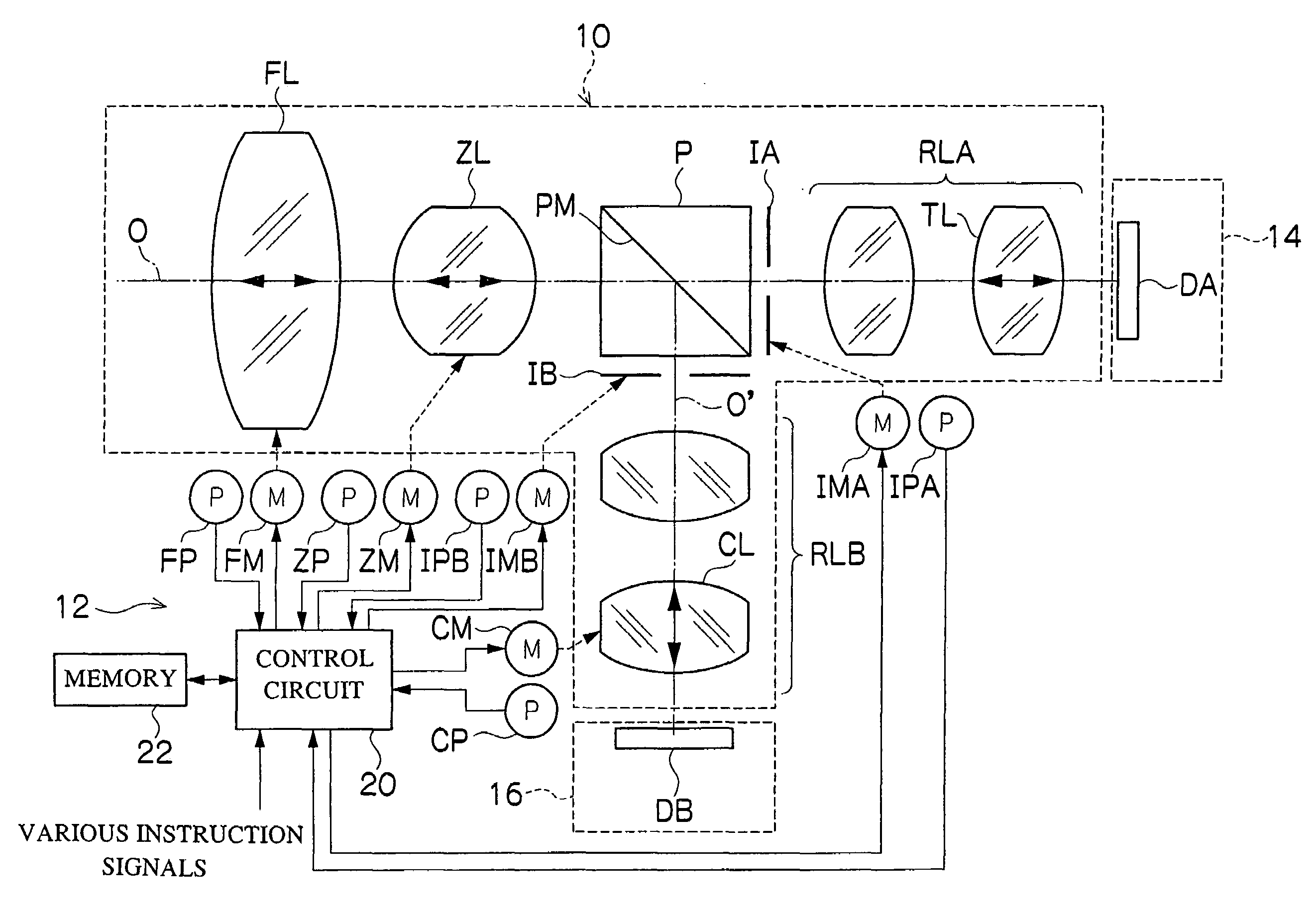
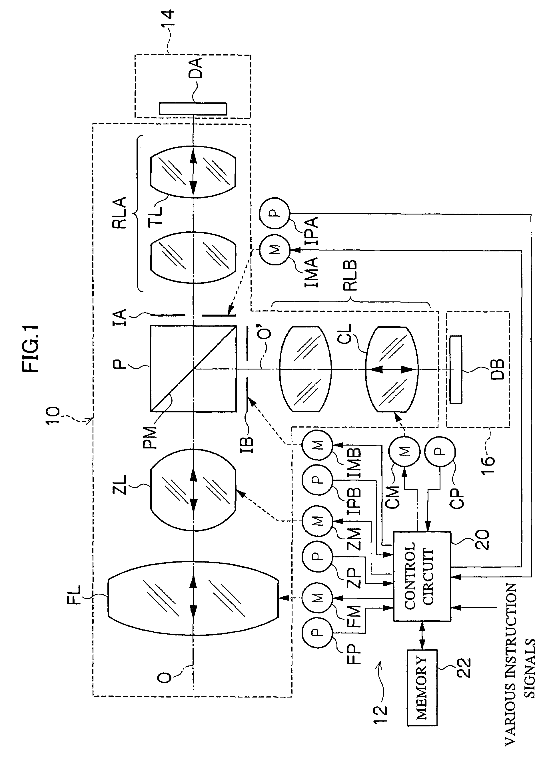
[0031]FIG. 1 is a view showing the general configuration of a lens system to which the present invention is applied. The lens system in this figure is used in a monitoring television camera or the like. It can photograph the same object simultaneously with a visible light and an infrared (near infrared) light. As shown in FIG. 1, the present lens system comprises a lens device composed of an optical system (photographing lens) 10 and a control system 12, a visible light camera main body 14 in which an image pickup element (CCD) DA picking up an image of an object using an object light in a visible light wavelength region (visible light region) is mounted, and an infrared light camera main body 16 in which an image pickup element (CCD) DB picking up an image of an object using an object...


PUM


Abstract

The present invention provides a visible and infrared light photographing lens system. A color separating prism or the like divides an object light entering a photographing lens and then passing through a focus lens, into an object light in a visible light region and an object light in an infrared light region. A visible light image pickup element and an infrared light image pickup element are used to pick up images of the respective object lights. Further, a compensation lens can be used to adjust a position where an image of the object light in the infrared light region is formed. Consequently, visible light photographing and infrared light photographing can be simultaneously carried out by focusing on an object at the same distance.

Description

BACKGROUND OF THE INVENTION[0001]1. Field of the Invention[0002]The present invention relates to a visible and infrared light photographing lens system, and in particular, to a visible and infrared light photographing lens system which enables the same object to be photographed simultaneously using a visible light and an infrared light.[0003]2. Description of the Related Art[0004]If a television camera (for example, a CCTV camera) is used to photograph images for monitoring or other applications, the photographing is carried out with a visible light in a bright environment such as in the daytime and with an infrared (near infrared) light in a dark environment such as in the nighttime when an object cannot be observed.[0005]In the prior art, a single camera may be used to carry out both visible light photographing and infrared light photographing. A camera is known in which a photographing lens installed in the camera main body need not be changed from one for a visible light to one ...

Claims


Application Information

Patent Timeline
Patent Type & Authority Patents(United States)
IPC IPC(8): G03B13/00G02B7/08G02B7/02G02B7/10G02B15/16G02B23/12G03B17/02G03B17/17G03B19/06H04N5/225H04N5/232H04N5/33
CPCG02B23/12H04N5/332H04N5/33H04N5/23212H04N23/67H04N23/11
Inventor KUWAKINO, KOSHIYAHAGI, SATOSHIHASEGAWA, TAKAMI
Owner FUJIFILM CORP
Why Eureka
Try Eureka