Method for predicting a power curve for a wind turbine

a technology of wind turbines and power curves, which is applied in the direction of process and machine control, electric generator control, electric devices, etc., can solve the problems of affecting the quality of power output predictions, affecting the efficiency of wind turbines, and over-estimating the power production in the partial load operation range of wind turbines, so as to achieve the effect of improving the quality of annual power output predictions and turbine control

a technology of wind turbines and power curves, which is applied in the direction of process and machine control, electric generator control, electric devices, etc., can solve the problems of affecting the quality of power output predictions, affecting the efficiency of wind turbines, and over-estimating the power production in the partial load operation range of wind turbines, so as to achieve the effect of improving the quality of annual power output predictions and turbine control

US7420289B2Active Publication Date: 2008-09-02GE INFRASTRUCTURE TECH INT LLC

Image

  • Method for predicting a power curve for a wind turbine
  • Method for predicting a power curve for a wind turbine
  • Method for predicting a power curve for a wind turbine

Examples


Embodiment Construction

[0022]Reference will now be made in detail to the various embodiments of the invention, one or more examples of which are illustrated in the figures. Each example is provided by way of explanation of the invention, and is not meant as a limitation of the invention. For example, features illustrated or described as part of one embodiment can be used on or in conjunction with other embodiments to yield yet a further embodiment. It is intended that the present invention includes such modifications and variations.

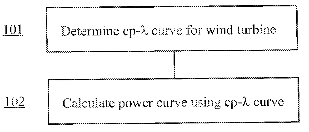
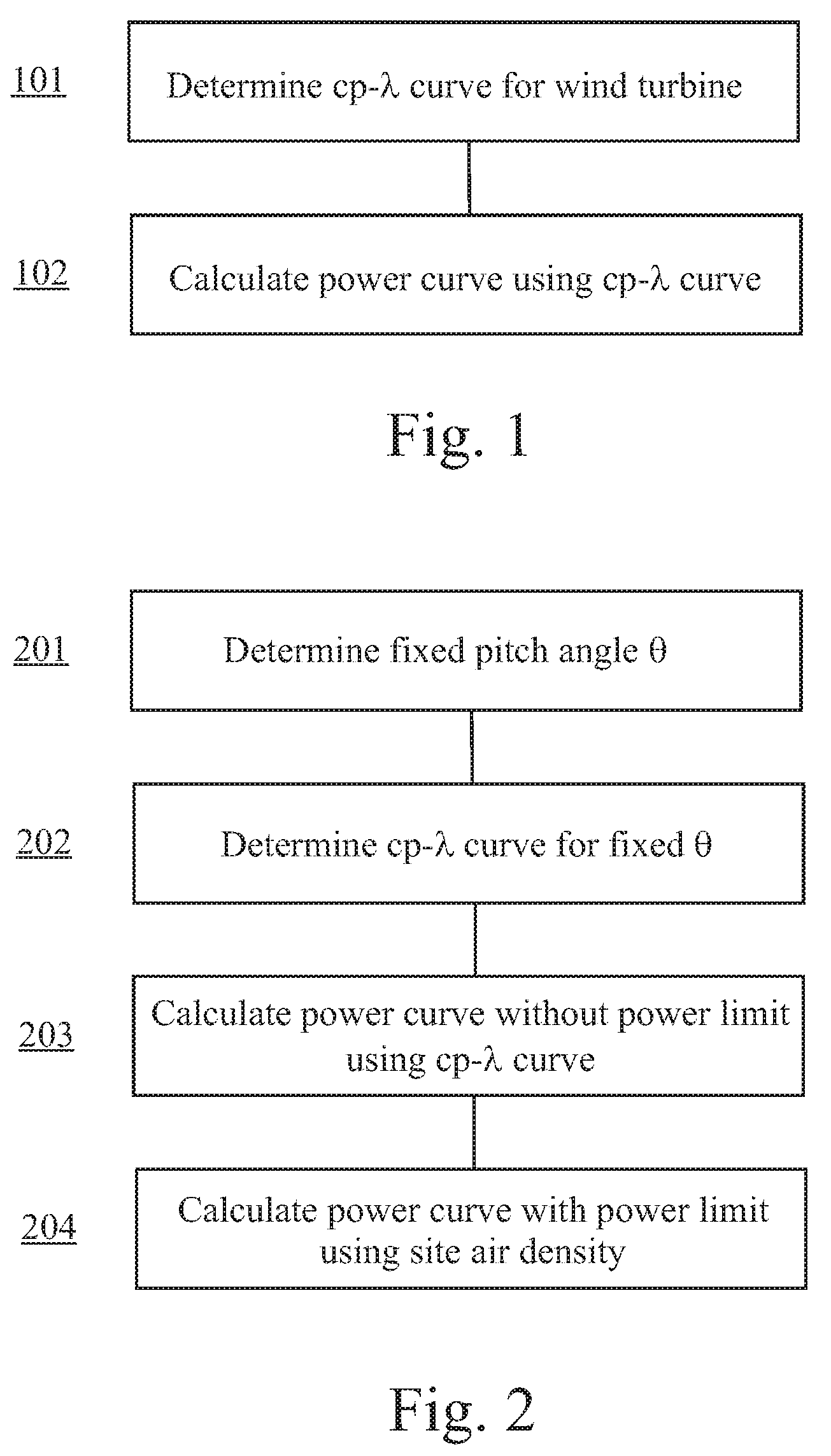
[0023]FIG. 1 shows a flow diagram of a method according to a first embodiment of the present invention. Therein, in a first step 101 a relation between the power coefficient cp and the tip-speed ratio λ is determined. This relation is typically called a cp-λ curve and is widely used for the characterization of wind turbines. In particular, the cp-λ curve will depend on the shape and number of the rotor blades as well as on the actual pitch angle of the blades. FIG. 4 shows seve...


PUM


Abstract

A method for calculating a high-altitude power curve for a wind turbine is provided, the method including the steps of determining a cp-λ curve for a predetermined blade pitch angle of said wind turbine; calculating a first power curve without power limit based on the cp-λ curve; and calculating the high-altitude power curve with power limit from said first power curve, thereby using a site air density.

Description

BACKGROUND OF THE INVENTION[0001]The present invention relates to a method for predicting a power curve for a wind turbine, especially to a method for obtaining a power curve adapted for high altitude operation of a wind turbine. Furthermore, the present invention is directed to a control strategy utilizing such power curve and to a wind turbine in which such control strategy is implemented.[0002]Wind turbines capture kinetic energy from the wind and convert it into electrical power. Since wind turbines can be designed as stand-alone or island solutions, they are especially suited to supply electric power to remote areas. For example, such areas may be located in mountainous regions or elevated plains, i.e. at high altitude. Due to their elevated location, wind turbines installed at those sites encounter a lower air density compared to sea level. The lower air density causes significant deviations from the “normal” operation at sea level. In particular, the power curve of the wind t...

Claims


Application Information

Patent Timeline
02 Sep 2008
Publication
US7420289B2
IPC
F03D9/00; H02P9/04
CPC
F03D7/028; F03D7/042; F05B2200/00; F05B2270/1011; Y02E10/723; F05B2270/324; F05B2270/335; F05B2270/504
Inventors
WANG, DONG; ZHOU, YU