Pipette

a pipette and pipette technology, applied in the field of pipette, can solve the problems of fatiguing the work of manual pipette, and achieve the effect of reducing the push of the control button

Active Publication Date: 2008-09-09
EPPENDORF SE
View PDF17 Cites 11 Cited by
  • Summary
  • Abstract
  • Description
  • Claims
  • Application Information

AI Technical Summary

Benefits of technology

[0013]Preferably, the movements of the plunger are electronically controlled in the dispensing mode. According to one form of realisation, the pipette has an equipment for locking the control button against any axial movement for this purpose. The control button serves only as a key head for the control of dispensing processes. According to a further form of realisation, the pipette has a switch, connected to the electric control system, for switching between a pipetting mode and a dispensing mode. According to a further form of realisation, the switch is coupled to the equipment for locking the control button, so that the dispensing mode is automatically switched on when the control button is locked. According to a further form of realisation, the equipment for locking has a spring element, which supports the control button in the axial direction against a push on the control button. Through this, the user does not push against a rigid stop. This is advantageous for the tactile sensation of the user.
[0015]According to one form of realisation, the electric control system does not apply any electric voltage to the electric drive motor when the pressure sensor indicates a reduced push on the control button. This makes it possible for the user to stop the pipette by reducing the push on the control button.
[0016]According to one form of realisation, the pipette has a downside stop, co-operating with the stopping bead of the lifting rod and which is supported by a spring, and the electric control system further relocates the driving spindle in the direction of the downside stop through the application of an electric voltage to the electric driving motor, when the stopping bead is in the stop situation with respect to the downside stop, when there is a push on the control button, indicated by the pressure sensor, so that the stopping bead springably presses the downside stop together. This makes it possible to perform an overstroke of the plunger, which causes ejection of residual liquid, by bearing down the spring resistance.

Problems solved by technology

Working with manual pipettes is fatiguing.

Method used


Image

  • Pipette
  • Pipette
  • Pipette

Examples


Embodiment Construction

[0033]While this invention may be embodied in many different forms, there are described in detail herein a specific preferred embodiment of the invention. This description is an exemplification of the principles of the invention and is not intended to limit the invention to the particular embodiment illustrated

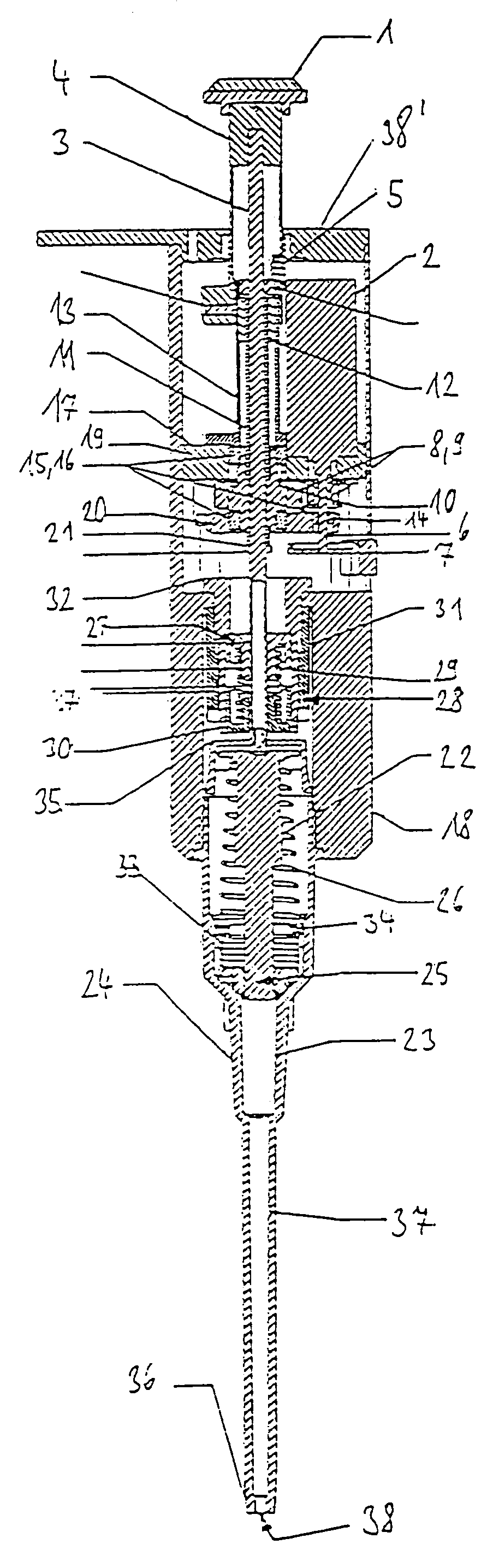
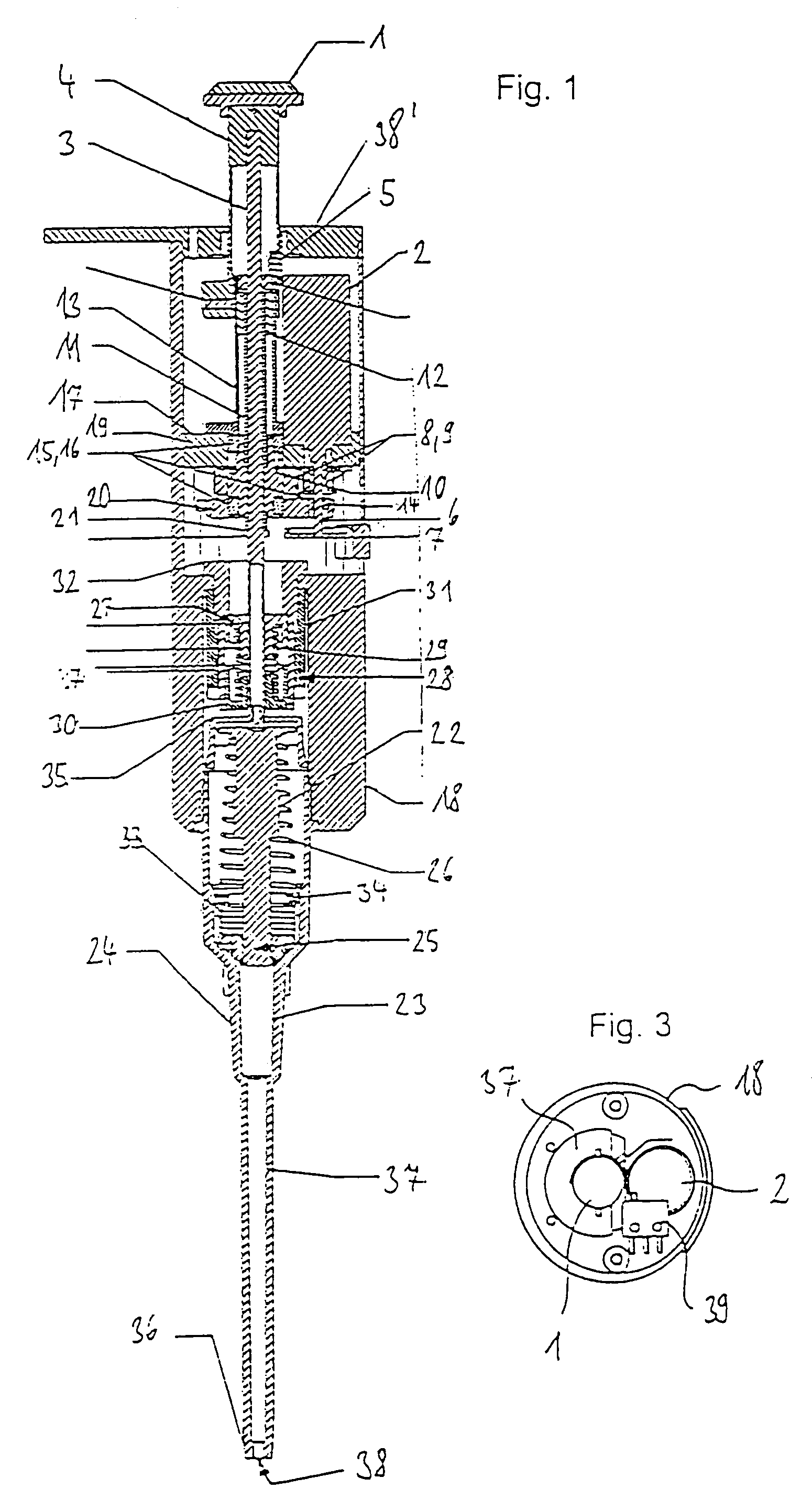
[0034]In the following description, the indications “upper and “lower” or “upside” and “downside”, respectively, are related to a substantially vertical orientation of the pipetting device, in which the control button is arranged upside and the pipette point is arranged downside, as is normally the case when liquid is picked up and given off.

[0035]The dosage equipment has a control button 1 with a not shown pressure sensor for simultaneous control of a driving motor 2 and of a lifting rod 3. The control button 1 has a button lower portion 4. The button lower portion 4 and the lifting rod 3 are loosely guided into one another and are kept in permanent bearing by a clearance com...


PUM


Abstract

Pipette having an axially relocatable control button, a pressure sensor, which is integrated into the control button, a lifting rod, coupled with the control button and having a stopping bead, a hollow driving spindle, accommodating the lifting rod and being axially relocatable, a twisting lock, preventing the driving spindle from being twisted, a turnable driving nut having screw thread engagement with the driving spindle, an axial support of the driving nut, an electric driving motor with a motor shaft, a gear between the motor shaft and the driving nut, an electric power supply, an electric control system, connected to the pressure sensor, the electric driving motor and the electric power supply, which provides an electric voltage to the electric driving motor upon a push on the control button which is indicated by the pressure sensor, so that the motor relocates the driving spindle via the gear in the direction of a relocation of the control button by the push, the driving spindle taking the lifting rod along with it on its stopping bead, a plunger, coaxially displaceable with respect to the lifting rod, a cylinder, connected to an opening which leads outward and in which the plunger is sealingly guided, and a plunger spring loading the plunger in the direction of an end of the lifting rod.

Description

CROSS-REFERENCE TO RELATED APPLICATIONS[0001]Not applicable.STATEMENT REGARDING FEDERALLY SPONSORED RESEARCH[0002]Not applicable.BACKGROUND OF THE INVENTION[0003]Pipettes are used in the laboratory for the dosage of liquids. They are known in different forms of realisation. Air cushion pipettes have an integrated cylinder with, a plunger arranged therein. The cylinder is connected to an opening in an attachment neck via a channel. A pipette point is detachably connectable with the attachment neck. Sample liquid is aspirated into the pipette point or ejected from it by displacing the plunger in the cylinder. In doing so, plunger and cylinder do not come into contact with the liquid, because the plunger moves the liquid indirectly via an air cushion. Only the pipette point, which is generally made of plastic material, is contaminated and can be exchanged after use.[0004]Direct displacement pipettes are detachably connected to a syringe, the plunger of which is drivable through the pip...

Claims


Application Information

Patent Timeline
Patent Type & Authority Patents(United States)
IPC IPC(8): B01L3/02
CPCB01L3/0227B01L3/0234B01L2200/146B01L2200/087
Inventor BELGARDT, HERBERTMOLITOR, PETERJAGDHUBER, BERND
Owner EPPENDORF SE
Why Eureka
Try Eureka