Anterior support device

a support device and anterior support technology, applied in the field of support devices, can solve the problems of many individuals suffering from lower back pain and dysfunction, back pain and disability, etc., and achieve the effects of reducing stress in the lower, middle and upper back, reducing stress, and prolonging productive li

Inactive Publication Date: 2008-09-09
PILGRIM INNOVATIONS
View PDF24 Cites 16 Cited by
  • Summary
  • Abstract
  • Description
  • Claims
  • Application Information

AI Technical Summary

Benefits of technology

[0010]The present invention meets the needs of the prior art by providing a device which supports an individual's spine while the individual is in a forward bent position. The device includes a padded rest on which an individual can lean while working in a forward bent position and support structure for adjusting the angle, height, and position of the device. Since the individual leans against the rest, the stresses experienced in the lower, middle, and upper back are substantially decreased. Reducing such stress decreases the pain experienced by the individual as well as extends his or her productive life.

Problems solved by technology

Many individuals suffer from lower back pain and dysfunction brought about by their work environment or other daily activities.
Repetitive or prolonged activities can be attributed as a major cause of this back pain and dysfunction.
This position contributes to posterior disc dysfunction, which leads to back pain and disability.
These devices, however, are designed to support the individual from the rear and thus are not effective for dentists and similar professionals who

Method used


Image

  • Anterior support device
  • Anterior support device
  • Anterior support device

Examples


embodiment 100

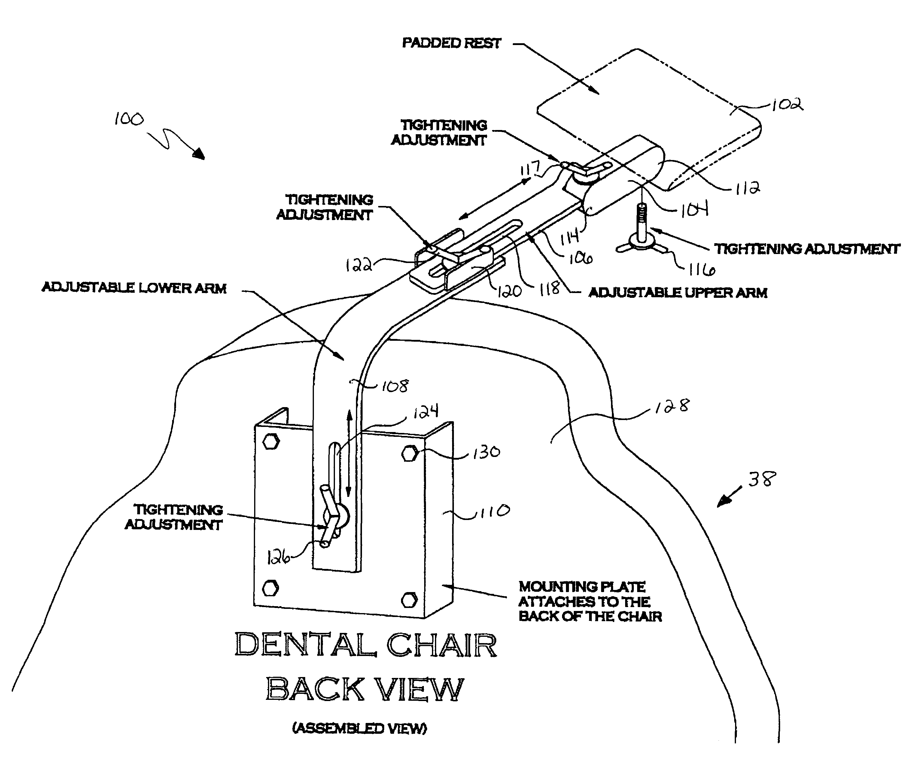
[0033]An alternate embodiment 100 of the present invention for use with a dental chair is shown in FIGS. 9-11. The alternate embodiment device 100 is similar to device 10 of FIG. 1, but differs in its relationship to dental chair 38. Instead of being attached to the base of dental chair 38, or to the floor, the device 100 is attached to the back 128 of the dental chair 38. As can be seen in FIG. 11, the device 100 can be rotated from one side of the dental chair 38 to the other, thereby providing flexibility by enabling the professional to work on either side of the patient. The device also allows the angle, height, and position of the rest to be adjusted, thereby providing further flexibility. Alternately, the present invention can be attached to other locations on dental chair 38, such as at a side of dental chair 38.

[0034]As depicted in FIGS. 9-11, the device 100 of this embodiment generally includes a padded rest 102, a pivot device 104, a first or upper arm 106, a second or low...

third embodiment

[0043]FIG. 12 provides an alternative third embodiment for mounting device 100 to dental chair 38. In this embodiment, device 100 can be provided on dental chair 38 during original equipment manufacture of the chair as well as being available as an after-market product. Accordingly, instead of using a mounting bracket 110, device 100 is attached to back 128 of dental chair 38 using a rotatable base 132. The rotatable base 132 can be integral with dental chair 38 or can be a separate device added to dental chair 38 during manufacture.

[0044]While rotatable base 132 is depicted in FIG. 12 as being positioned substantially in the center of back 128 relative to the sides of dental chair 38, rotatable base 132 can be positioned anywhere on back 128. Additionally, rotatable base 132 can be attached to other locations on dental chair 38, such as a side of dental chair 38.

[0045]The rotatable base 132 comprises rotation structure which enables device 100 to be rotated (as shown in the dotted ...

embodiment 80

[0050]FIG. 5 depicts yet a further embodiment 80 of the present invention for use in gardening or activities involving kneeling. Such a device can include a padded rest 82, a vertical adjustable bracket 84, and a footplate 86 at the lower end of bracket 84. A neck or shoulder strap 88 can be attached to the support device, as shown at padded rest 82, for carrying the device thereby allowing the user to change positions without the use of his hands.

[0051]The device can be provided with a coupling 90 between rest 82 and bracket 84 to vary the angle of rest 82 with respect to bracket 84. In addition, a coupling 92 can also be provided between bracket 84 and footplate 86. These couplings can take the form of a ball swivel with a screw pivot, similar to that shown in FIG. 6. The bracket 84 can also be provided with the telescoping feature, shown in FIGS. 7a and 7b, to enable the height of the bracket 84 to be adjusted.


PUM


Abstract

The present invention is directed to a device which supports a user's spine while the user is in a forward bent position. The device includes a padded rest on which the user can lean while working in a forward bent position, and support structure enabling at least three of lateral adjustment of the rest along the projected perimeter of the work area, adjustment of the rest across the projected perimeter, height adjustment of the rest, and angular orientation of the rest. Since the user leans against the rest, the stresses otherwise normally experienced in the lower, middle and upper back are substantially attenuated. Attenuating such stress attenuates the pain experienced by the user as well as potentially extending his or her productive life.

Description

RELATED APPLICATIONS[0001]This application is a continuation-in-part application of U.S. patent application Ser. No. 10 / 180,621, filed on Jun. 26, 2002, which is a divisional of U.S. patent application Ser. No. 09 / 932,041, filed on Aug. 17, 2001, now U.S. Pat. No. 6,435,186, the entirety of the previously filed applications being incorporated herein by reference.FIELD OF THE INVENTION[0002]The present invention is directed generally to a support device and specifically to an anterior support device for use in the health care industry.BACKGROUND OF THE INVENTION[0003]Many individuals suffer from lower back pain and dysfunction brought about by their work environment or other daily activities. Repetitive or prolonged activities can be attributed as a major cause of this back pain and dysfunction. Effected individuals must drastically modify their work areas in order to continue their jobs. In many instances, people must choose another field of employment.[0004]One such example is dent...

Claims


Application Information

Patent Timeline
Patent Type & Authority Patents(United States)
IPC IPC(8): A61G15/00A61B19/00A61G15/08
CPCA61B19/28A61G15/08A61B90/60
Inventor KLEMM, KURT
Owner PILGRIM INNOVATIONS
Why Eureka
Try Eureka