Forward blunting wingset with leaf spring driven shield

a shield and shield technology, applied in the field of safety needle devices, can solve the problems of repeated use of a relatively expensive holder, difficult manufacturing of prior art devices, and complex operation

Active Publication Date: 2008-09-09
BECTON DICKINSON & CO
View PDF58 Cites 35 Cited by
  • Summary
  • Abstract
  • Description
  • Claims
  • Application Information

AI Technical Summary

Benefits of technology

[0012]The drive mechanism preferably includes a mechanism, such as a locking lug, which is capable of frictional or abutting engagement with the housing for retaining the drive mechanism in a biased state between the first lateral extension and the second lateral extension when the tip guard is in the retracted position. In addition, a release latch may be provided for releasing the locking lug from engagement with the housing, thereby causing the drive mechanism to release energy and bias the tip guard to the extended position.

Problems solved by technology

Thus, these blood collection devices allow repeated use of a relatively expensive holder upon replacement of relatively inexpensive medical needles and / or fluid collection tubes.
Such prior art devices are typically difficult to manufacture and require complex operation to operate.

Method used


Image

  • Forward blunting wingset with leaf spring driven shield
  • Forward blunting wingset with leaf spring driven shield
  • Forward blunting wingset with leaf spring driven shield

Examples


Embodiment Construction

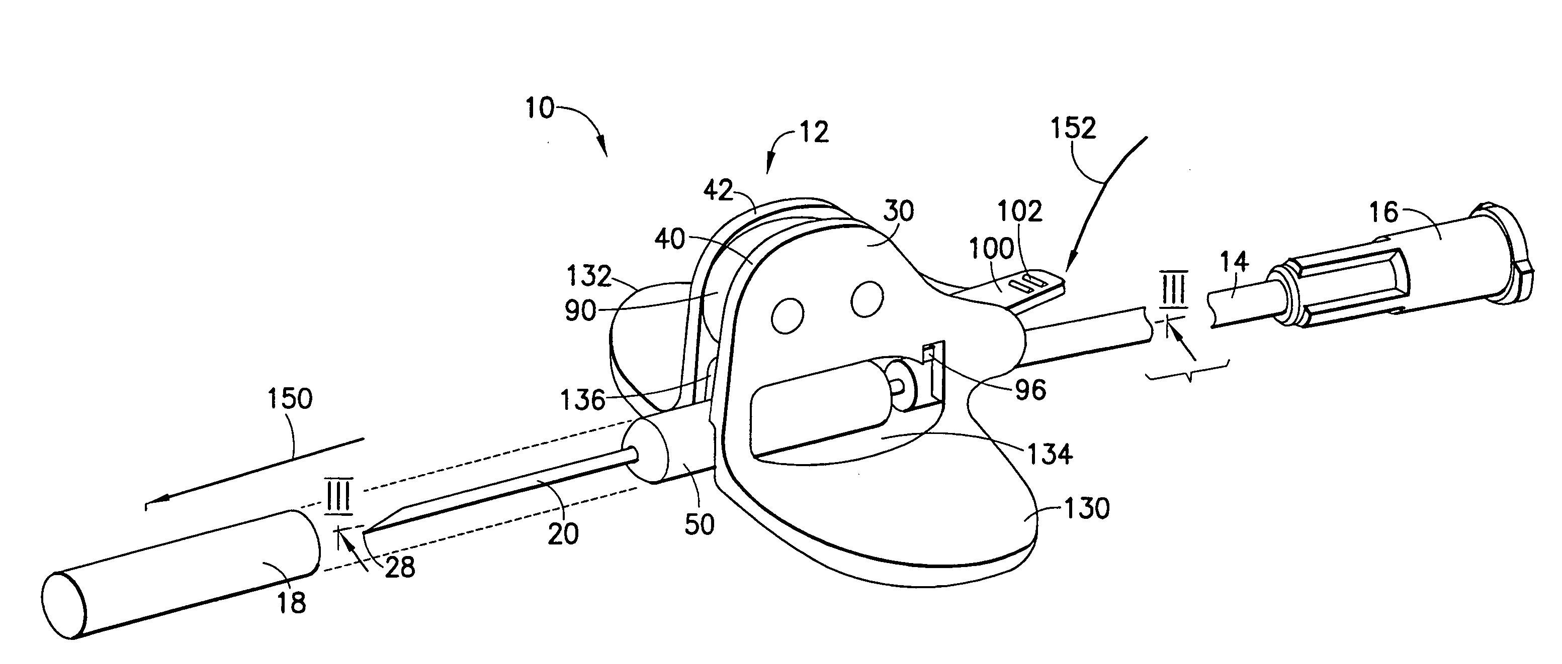
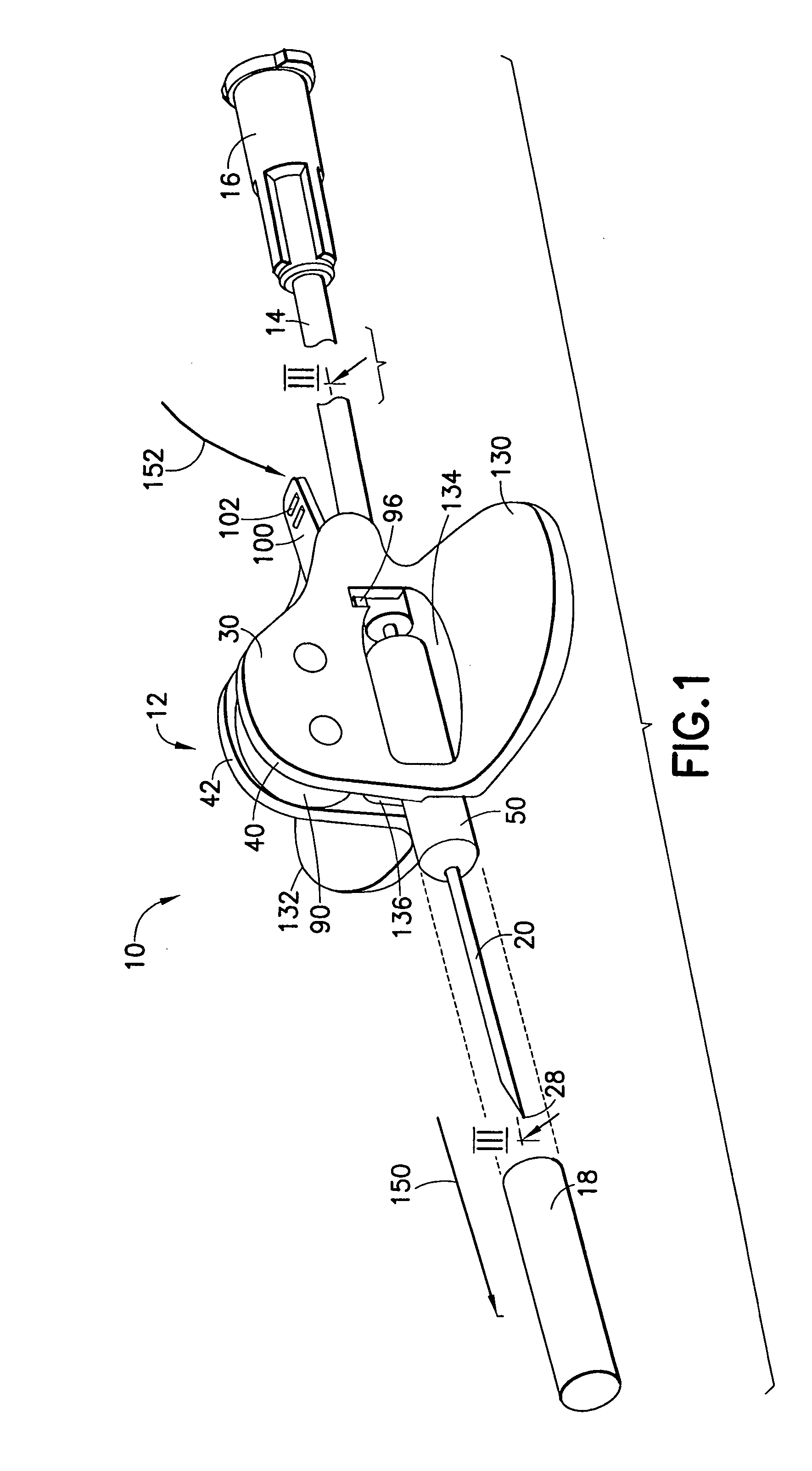
[0029]Referring to the drawings in which like reference characters refer to like parts throughout the several views thereof, FIG. 1 illustrates a blood collection set in the form of a wingset including a shieldable needle device, in accordance with the present invention and the related features. The present invention is generally described in terms of a shieldable needle device. FIG. 1 illustrates the shieldable needle device in the form of a blood collection set 10 including a shieldable needle device 12. While described herein in terms of one embodiment of a blood collection set, the shieldable needle device of the present invention may be used with or incorporate other medical devices used in connection with a needle, such as a hypodermic syringe assembly, a hypodermic needle, a double-ended needle assembly for blood collection, an intravenous infusion set, or other handling devices or medical device assemblies that contain piercing elements.

[0030]As shown in FIG. 1, blood collec...


PUM


Abstract

A shieldable needle device is provided. The shieldable needle device includes a housing, a needle cannula, a tip guard and a flexibly resilient drive mechanism. The housing includes a first lateral extension and a second lateral extension which are interconnected at a rearward end to form a hub portion from which the needle cannula extends. The tip guard telescopes over the needle cannula from a retracted position to an extended position. The drive mechanism is attached to the tip guard and is bent or coiled within the housing between the first and second lateral extension and retained in the bent or coiled position. Upon release of the drive mechanism, the tip guard is moved from a retracted position to an extended position, thereby protectively surrounding a tip of the needle cannula.

Description

CROSS-REFERENCE TO RELATED APPLICATION[0001]This application claims priority to U.S. Provisional Patent Application No. 60 / 435,634 filed Dec. 19, 2002.BACKGROUND OF THE INVENTION[0002]1. Field of the Invention[0003]The present invention relates to safety needle devices for safe and convenient handling of needles. More particularly, the present invention relates to a shieldable needle device having a forward moving safety shield for protection from a used needle tip.[0004]2. Description of Related Art[0005]Disposable medical devices having medical needles are used for administering medication or withdrawing fluid from the body of a patient. Such disposable medical devices typically include blood-collecting needles, fluid handling needles and assemblies thereof. Current medical practice requires that fluid containers and needle assemblies used in such devices be inexpensive and readily disposable. Consequently, existing blood collection devices typically employ some form of durable, r...

Claims


Application Information

Patent Timeline
Patent Type & Authority Patents(United States)
IPC IPC(8): A61M5/00A61M5/32A61B5/145A61B5/15
CPCA61B5/14A61B5/1411A61M25/0625A61M25/0637A61M5/3257A61M2005/325A61M2005/3249A61M5/3275A61B5/15003A61B5/150259A61B5/150389A61B5/150473A61B5/150503A61B5/150564A61B5/150572A61B5/150587A61B5/150656A61B5/150717A61B5/15074A61B5/153
Inventor WILKINSON, BRADLEYNEWBY, C. MARK
Owner BECTON DICKINSON & CO
Why Eureka
Try Eureka