Eureka AIR delivers breakthrough ideas for toughest innovation challenges, trusted by R&D personnel around the world.

Motor Driving Control Method And Motor Driving Control Device

一种电机驱动控制、驱动控制的技术,应用在单相电机控制、单个电动机转速/转矩控制、励磁或电枢电流控制等方向,能够解决不能电机线圈能量释放、电机振动等问题,达到抑制振动、抑制反冲现象的效果

Active Publication Date: 2015-12-23
MINEBEAMITSUMI INC
View PDF5 Cites 3 Cited by
  • Summary
  • Abstract
  • Description
  • Claims
  • Application Information

AI Technical Summary

Problems solved by technology

However, when the regenerated energy is relatively large, even using these control steps, the energy accumulated in the motor coil cannot be effectively released.
Therefore, there is a problem that the motor vibrates and generates noise due to the backlash phenomenon

Method used


Image

  • Motor Driving Control Method And Motor Driving Control Device
  • Motor Driving Control Method And Motor Driving Control Device
  • Motor Driving Control Method And Motor Driving Control Device

Examples


no. 1 approach

[0044] (Configuration of the first embodiment)

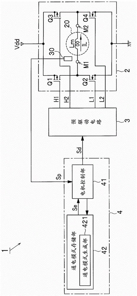
[0045] figure 1 It is a schematic configuration diagram showing the motor drive control device 1 in this embodiment.

[0046] Such as figure 1 As shown, the motor drive control device 1 controls the drive of a motor 20 which is a single-phase brushless motor. The motor 20 includes, for example, a position detector 30 as a Hall element and a motor coil Lm. This motor drive control device 1 includes a control circuit unit 4 , a pre-drive circuit 3 , and an H-bridge circuit 2 .

[0047] The control circuit unit 4 includes a motor control unit 41 and an energization pattern generation unit 42 . The control circuit unit 4 generates a drive control signal Sd based on the position detection signal Sp (position information) from the position detector 30 and outputs it to the pre-driver circuit 3 .

[0048] The energization pattern generation unit 42 includes an energization pattern storage unit 421 . The energization pattern gen...


PUM


Abstract

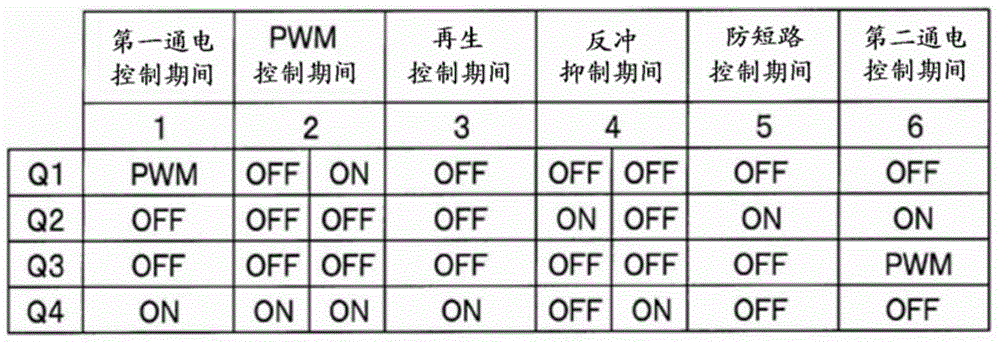
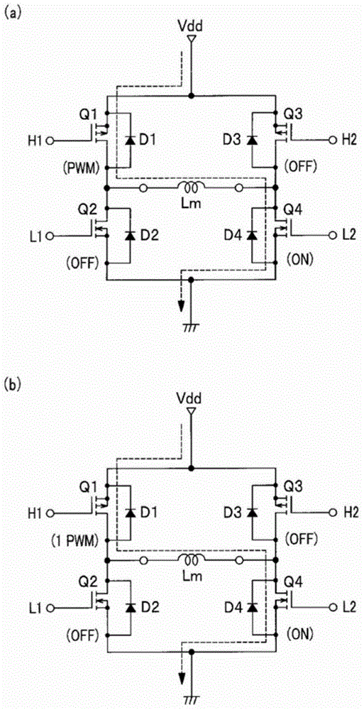
An H-bridge circuit controls a motor and includes a first series circuit of switching elements and a second series circuit of switching elements connected in parallel to the first series circuit. A motor driving control method includes a step of turning each of the switching elements Q2, Q3 off and turning-on or performing PWM control on the switching element Q1 and also turning the switching elements Q4 on; a step of performing PWM control on Q1; a step of turning off Q1; a step of repeating for a predetermined number of times a first kickback suppression period during which Q2 is turned on and Q4 is turned off and a second kickback suppression period during which Q2 is turned off and Q4 is turned on; and a step of turning Q2 on and turning on or performing PWM control on Q3.

Description

technical field [0001] The present invention relates to a drive control method and a motor drive control device for driving the motor by passing a current through a coil of the motor. Background technique [0002] The driving control method of a single-phase motor will be described below. [0003] Figure 10 is a schematic configuration diagram showing a motor drive control device of a comparative example. [0004] Such as Figure 10 As shown, the motor drive control device 101 of the comparative example controls the drive of the motor 20 which is a single-phase brushless motor. The motor 20 includes, for example, a position detector 30 as a Hall element and a motor coil Lm. This motor drive control device 101 includes a control circuit unit 104 , a pre-drive circuit 103 , and an H-bridge circuit 102 . [0005] The control circuit unit 104 generates a drive control signal Sd based on the position detection signal Sp (position information) from the position detector 30 and...

Claims


Application Information

Patent Timeline
Patent Type & Authority Applications(China)
IPC IPC(8): H02P7/28H02P6/08H02P6/16
CPCH02P6/14H02P6/26
Inventor 青木政人
Owner MINEBEAMITSUMI INC
Why Eureka
Eureka Blog
Learn More