LED driving device of overvoltage protection and duty control

a driving device and protection technology, applied in the direction of electric variable regulation, process and machine control, instruments, etc., can solve the problems of low response speed, low color reproduction characteristics, and difficulty in reducing weight, thickness, and size of an lcd panel

Active Publication Date: 2008-09-09
SAMSUNG ELECTRONICS CO LTD
View PDF10 Cites 29 Cited by
  • Summary
  • Abstract
  • Description
  • Claims
  • Application Information

AI Technical Summary

Problems solved by technology

In general, since a cold cathode fluorescent lamp (CCFL) used for a light source of a backlight of a liquid crystal display (LCD) uses mercury gas, environmental pollution may be caused, response speed is low, color reproduction characteristics is low, and it is difficult to reduce weight, thickness, and size of an LCD panel.
Though the brightness can be controlled by using a variable resistor for a voltage detection resistor Rs, since a wattage resistor has to be used as the voltage detection resistor Rs due to a high Led resistance, variableness is difficult.
Since a variation occurs in a value of the voltage detection resistor Rs for each driving circuit, controlling brightness, color coordinates, and uniformity is difficult.
However, in the LED driving circuit 10 employing the boost type DC-DC converter, since a duty of an output signal does not perfectly become 0% due to characteristics of the current-mode PWM driving IC, LEDs are slightly lighted when to turn off LEDs.

Method used


Image

  • LED driving device of overvoltage protection and duty control
  • LED driving device of overvoltage protection and duty control
  • LED driving device of overvoltage protection and duty control

Examples


Embodiment Construction

[0023]Exemplary embodiments of the present invention will now be described in detail with reference to the accompanying drawings.

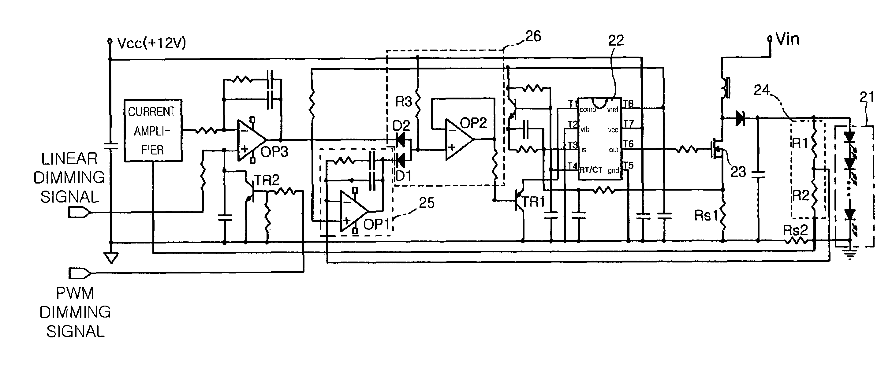
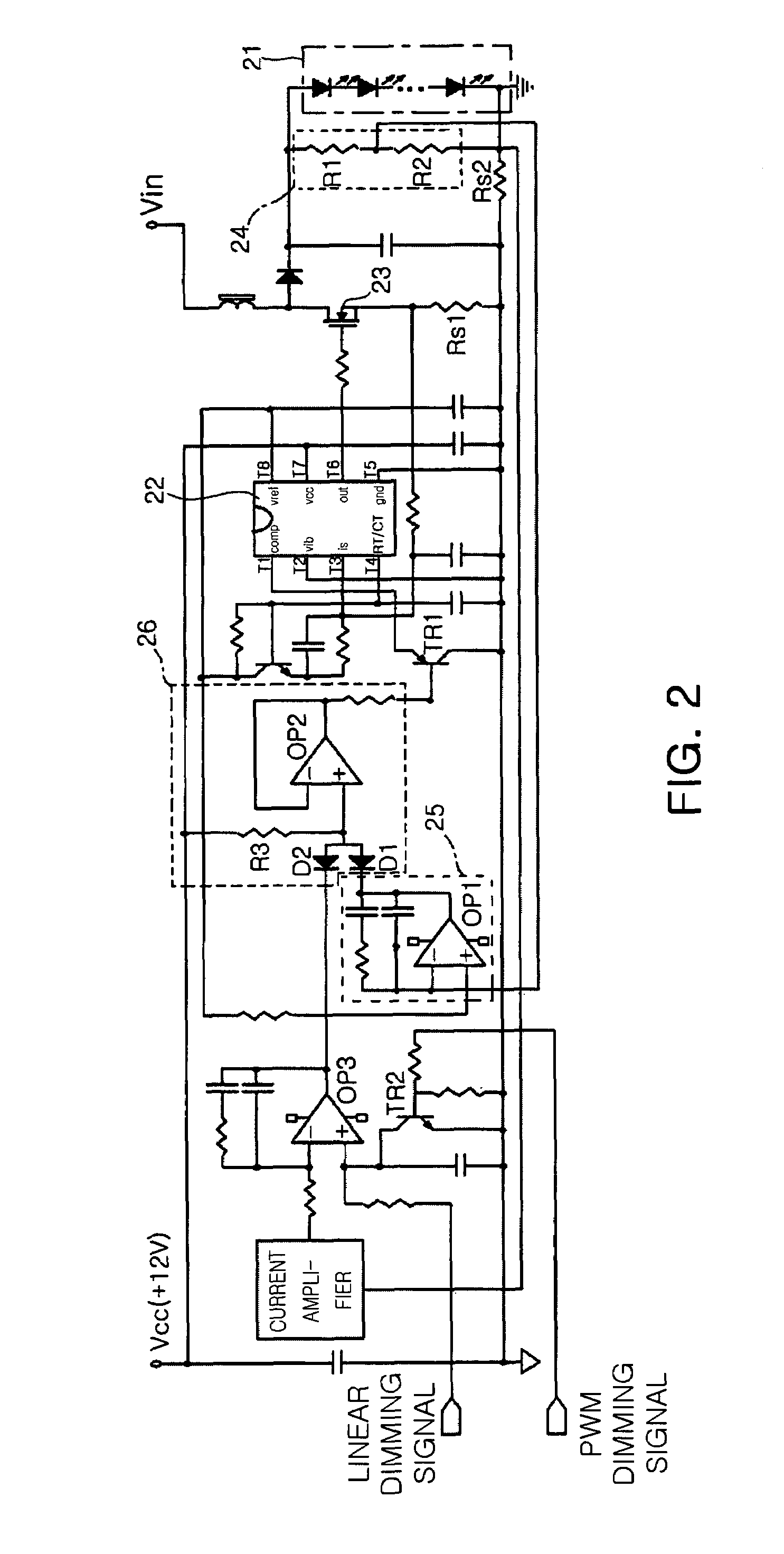
[0024]FIG. 2 is a circuit diagram illustrating an LED driving device having functions of overvoltage protection and duty control, according to an exemplary embodiment of the present invention. Referring to FIG. 2, the LED driving device includes an LED array 21 including a plurality of LEDs electrically connected to each other; a PWM IC 22 including an RT / CT terminal T4 operated by a power voltage Vcc and generating and outputting a sawtooth wave voltage of a predetermined frequency, a COMP terminal T1 to which a comparison voltage compared with the sawtooth wave voltage is inputted, and an output terminal T6 generating and outputting a pulse signal turned off in a section in which a level of the sawtooth wave voltage is higher than a level of the comparison voltage and turned on in a section in which the level of the sawtooth voltage is lower than the lev...


PUM


Abstract

An LED driving device comprises a PWM IC including an RT / CT terminal operated by a power voltage and generating and outputting a sawtooth wave voltage of a predetermined frequency, a COMP terminal to which a comparison voltage compared with the sawtooth wave voltage is inputted, and an output terminal generating and outputting a pulse signal turned off in a section in which a level of the sawtooth wave voltage is higher than a level of the comparison voltage and turned on in a section in which the level of the sawtooth voltage is lower than the level of the comparison voltage. The LED driving device sets up the comparison voltage inputted to the COMP terminal of the PWM IC to be 0 when an error voltage corresponding to a difference between a both end voltage of an LED array and a predetermined reference voltage is less than a predetermined level.

Description

CLAIM OF PRIORITY[0001]This application claims the benefit of Korean Patent Application No. 2006-36900 filed on Apr. 24, 2006, in the Korean Intellectual Property Office, the disclosure of which is incorporated herein by reference.BACKGROUND OF THE INVENTION[0002]1. Field of the Invention[0003]The present invention relates to an LED driving device, and more particularly, to an LED driving device employing a boost type direct current (DC)-DC converter, capable of protecting an LED and a driving circuit from an overvoltage loaded on the LED and controlling a duty of an output signal of a current-mode pulse with modulation (PWM) driving IC employed by the boost type DC-DC converter to be perfect 0%.[0004]2. Description of the Related Art[0005]In general, since a cold cathode fluorescent lamp (CCFL) used for a light source of a backlight of a liquid crystal display (LCD) uses mercury gas, environmental pollution may be caused, response speed is low, color reproduction characteristics is...

Claims


Application Information

Patent Timeline
Patent Type & Authority Patents(United States)
IPC IPC(8): H05B37/02H02H3/20H05B44/00H01L33/00
CPCH05B33/0818H05B33/0851H05B33/0884Y02B20/346Y02B20/341H05B45/50H05B45/10Y02B20/30H05B45/38H02M3/155G02F1/133
Inventor LEE, SANG YUN
Owner SAMSUNG ELECTRONICS CO LTD
Why Eureka
Try Eureka