Waveguide horn antenna array and radar device

a technology of horn antenna array and radar device, which is applied in the direction of linear waveguide fed array, antenna, electrical apparatus, etc., can solve the problems of propagation signal (electromagnetic wave) leakage from the feed waveguide to the coupling waveguide, and achieve the effect of wide adjustment range of coupling degree and simple structur

Inactive Publication Date: 2008-09-09
MURATA MFG CO LTD
View PDF7 Cites 163 Cited by
  • Summary
  • Abstract
  • Description
  • Claims
  • Application Information

AI Technical Summary

Benefits of technology

[0008]Accordingly, it is an object of the present invention to provide a waveguide horn antenna array in which the adjustment range of the degree of coupling is wide and the structure is simple.

Problems solved by technology

When a signal is propagated to the feed waveguide, the propagation signal (electromagnetic wave) leaks from the feed waveguide to the coupling waveguides due to disturbance of the signal transmission line caused by the coupling space area.

Method used


Image

  • Waveguide horn antenna array and radar device
  • Waveguide horn antenna array and radar device
  • Waveguide horn antenna array and radar device

Examples


Embodiment Construction

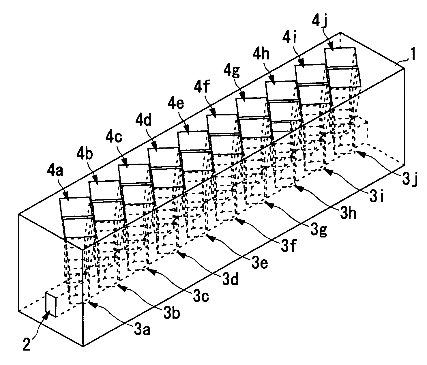
[0053]A waveguide horn antenna array according to an embodiment of the present invention is described with reference to FIGS. 1 to 15.

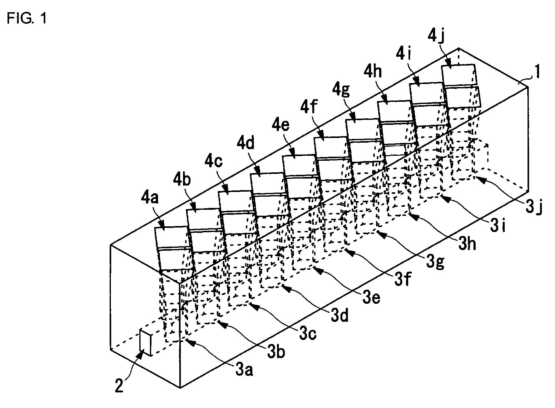
[0054]FIG. 1 is an external perspective view showing the outline of the structure of a waveguide horn antenna array of the present invention. FIG. 2 is a partially expanded perspective view of the waveguide horn antenna array shown in FIG. 1. FIG. 3A is a partially expanded top view of the waveguide horn antenna array shown in FIG. 1, and FIG. 3B is a sectional view taken along line A-A′ in FIG. 3A.

[0055]The waveguide horn antenna array of the present invention contains a feed waveguide 2 extending in a fixed direction and horn antennas 3a to 3j and 4a to 4j each coupled to the feed waveguide 2. The feed waveguide 2 and the horn antennas 3a to 3j and 4a to 4j are formed in a conductor member 1.

[0056]The feed waveguide 2 extends in a fixed direction and is formed in accordance with the shape of the conductor member 1, and the section perpendicular to t...


PUM


Abstract

A conductor member contains a linear feed waveguide extending in a fixed direction and a plurality of horn antennas coupled to the feed waveguide and set at an interval of about one half of a wavelength in the extending direction of the feed waveguide. The horn antennas are formed by horns and coupling waveguides, and the coupling waveguides are set so as to partially enter the feed waveguide. When the size of the spatial coupling portion formed by the entrance is changed, the degree of coupling between the feed waveguide and each of the coupling waveguides changes.

Description

BACKGROUND OF THE INVENTION[0001]1. Field of the Invention[0002]The present invention relates to a waveguide horn antenna array having a plurality of waveguide horn set in a feed waveguide with a fixed arrangement pattern and a radar device for performing target detection by using the antenna.[0003]2. Description of the Related Art[0004]In radar devices, etc., using the millimeter waveband, by utilizing the fact that transmission loss is less in waveguides than in planar circuits such as microstrip lines, etc., waveguide antenna arrays are used more than planar-circuit type antenna arrays.[0005]Among related waveguide antenna arrays, as shown in Japanese Unexamined Patent Application Publication No. 10-32423, a connection waveguide is connected by T-branching in a perpendicular manner to one wall surface of a feed waveguide. Furthermore, as shown in Japanese Unexamined Patent Application Publication No. 2000-9822, the extending direction of a feed waveguide is perpendicular to the e...

Claims


Application Information

Patent Timeline
Patent Type & Authority Patents(United States)
IPC IPC(8): H01Q13/00
CPCH01Q21/064H01Q21/0037
Inventor NAGAI, TOMOHIRO
Owner MURATA MFG CO LTD
Why Eureka
Try Eureka