Transflective liquid crystal display device having alignment film covering plural isolated stacks of resin and diffusive reflective plate layers

a liquid crystal display device and alignment film technology, applied in closed circuit television systems, instruments, television systems, etc., can solve the problems of reducing the contrast in the transmissive mode and the iridescence phenomenon

Inactive Publication Date: 2008-09-09
INNOLUX CORP
View PDF6 Cites 17 Cited by
  • Summary
  • Abstract
  • Description
  • Claims
  • Application Information

AI Technical Summary

Benefits of technology

[0012]According to this arrangement, the diffusing optical element functions in a scattering state in the reflective mode, and can thereby diffuse light rays in the same optical path direction which may causes interferences produced on an uneven surface of a diffusive reflective plate in the reflective mode and thereby change their optical path directions and avoid a phenomenon of iridescence caused by interference of light rays. Furthermore, the diffusing optical element also functions in a non-scattering state in the transmissive mode, and can thereby prevent light from being diffused and prevent contrast from being reduced in the transmissive mode.
[0015]According to this arrangement, the glass substrate is not arranged on the top layer, which eliminates the need for forming an antireflective film on the surface of the glass substrate or applying antireflective treatment.

Problems solved by technology

In a transflective liquid crystal display device having a diffusive reflective plate, when incident light is reflected on the uneven surface of the diffusive reflective plate, different light rays in the same optical path direction are produced on one convex part of the uneven surface; light rays near the vertex of the convex part and light rays near the valley of the convex part, which interfere with one another causing a phenomenon of iridescence.
However, the above described transflective liquid crystal display device has a problem that due to the polarizer subjected to anti-glare treatment or the adhesive glue having a diffusive characteristic, and a diffusive adhesive glue in particular, transmissive light is diffused in a transmissive mode and contrast in the transmissive mode is thereby reduced.

Method used


Image

  • Transflective liquid crystal display device having alignment film covering plural isolated stacks of resin and diffusive reflective plate layers
  • Transflective liquid crystal display device having alignment film covering plural isolated stacks of resin and diffusive reflective plate layers
  • Transflective liquid crystal display device having alignment film covering plural isolated stacks of resin and diffusive reflective plate layers

Examples


embodiment 1

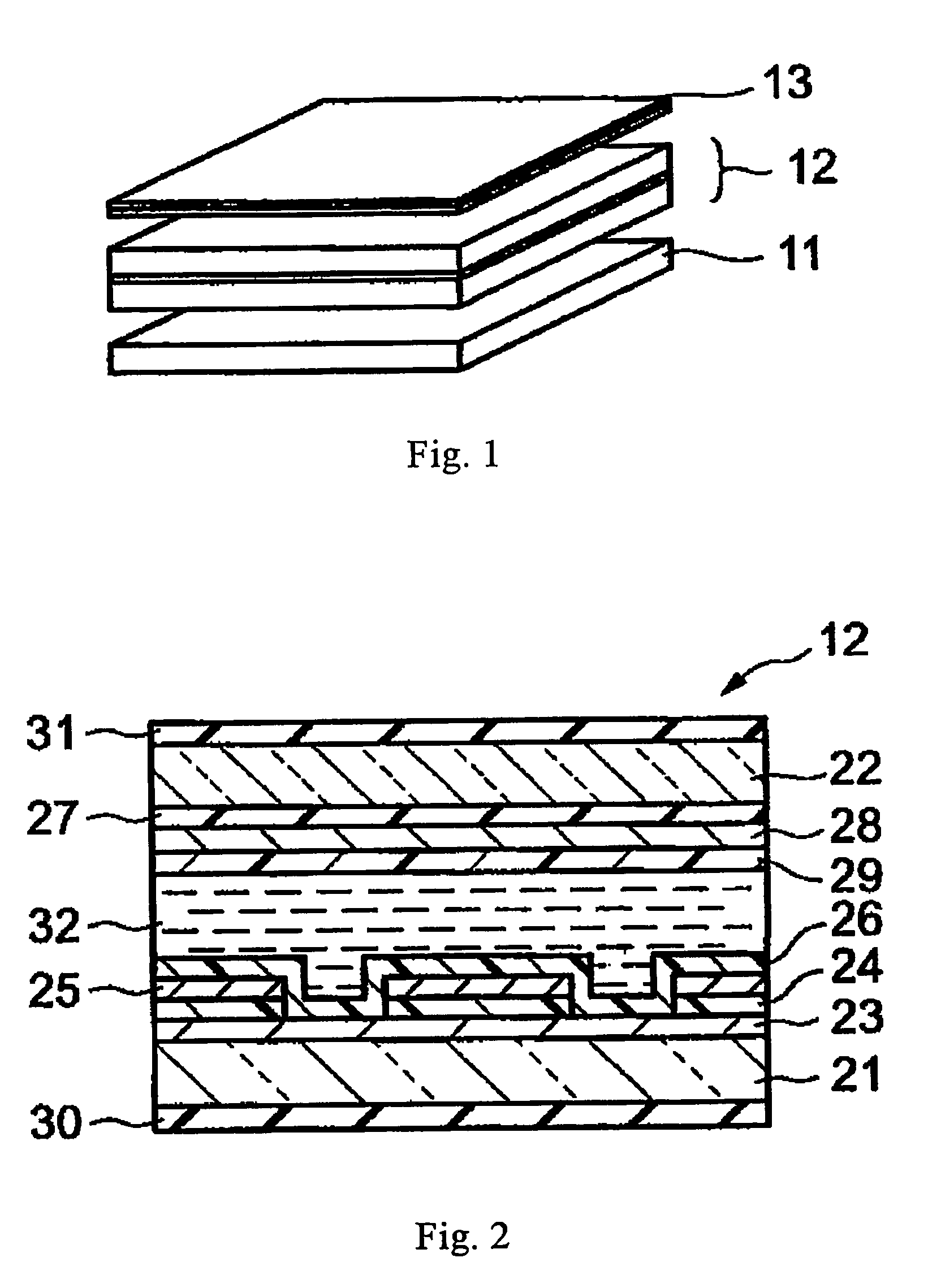
[0025]This embodiment will describe an arrangement of a diffusing optical element arranged over a liquid crystal panel which can be changed such that it has a scattering state in a reflective mode and a non-scattering state in a transmissive mode. FIG. 1 is a view showing an arrangement of the transflective liquid crystal display device according to Embodiment 1 of the present invention.

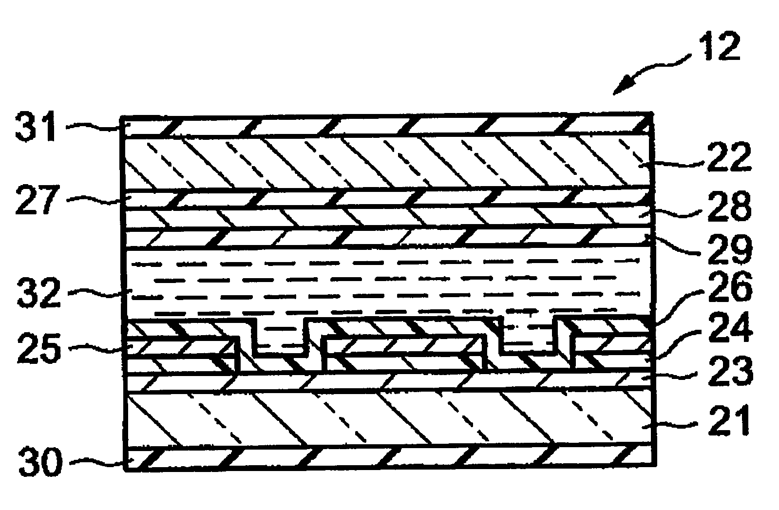
[0026]The transflective liquid crystal display device shown in FIG. 1 is principally constructed of a backlight 11 which is a light source used in the transmissive mode, a liquid crystal panel 12 arranged over this backlight 11 for functioning as a display element and a diffusing optical element 13 which can be changed so as to have a scattering state in the reflective mode and a non-scattering state in the transmissive mode.

[0027]As the backlight 11, one used for a normal liquid crystal display device can be used.

[0028]As the liquid crystal panel 12, a liquid crystal panel used for a monochrome tran...

embodiment 2

[0050]This embodiment will describe an arrangement with the diffusing optical element 13 incorporated in the liquid crystal panel 12. FIG. 6 is a sectional view showing an arrangement of the liquid crystal panel of the transflective liquid crystal display device according to Embodiment 2 of the present invention. In FIG. 6, the same parts as those in FIG. 2 are assigned the same reference numerals and detailed explanations thereof will be omitted.

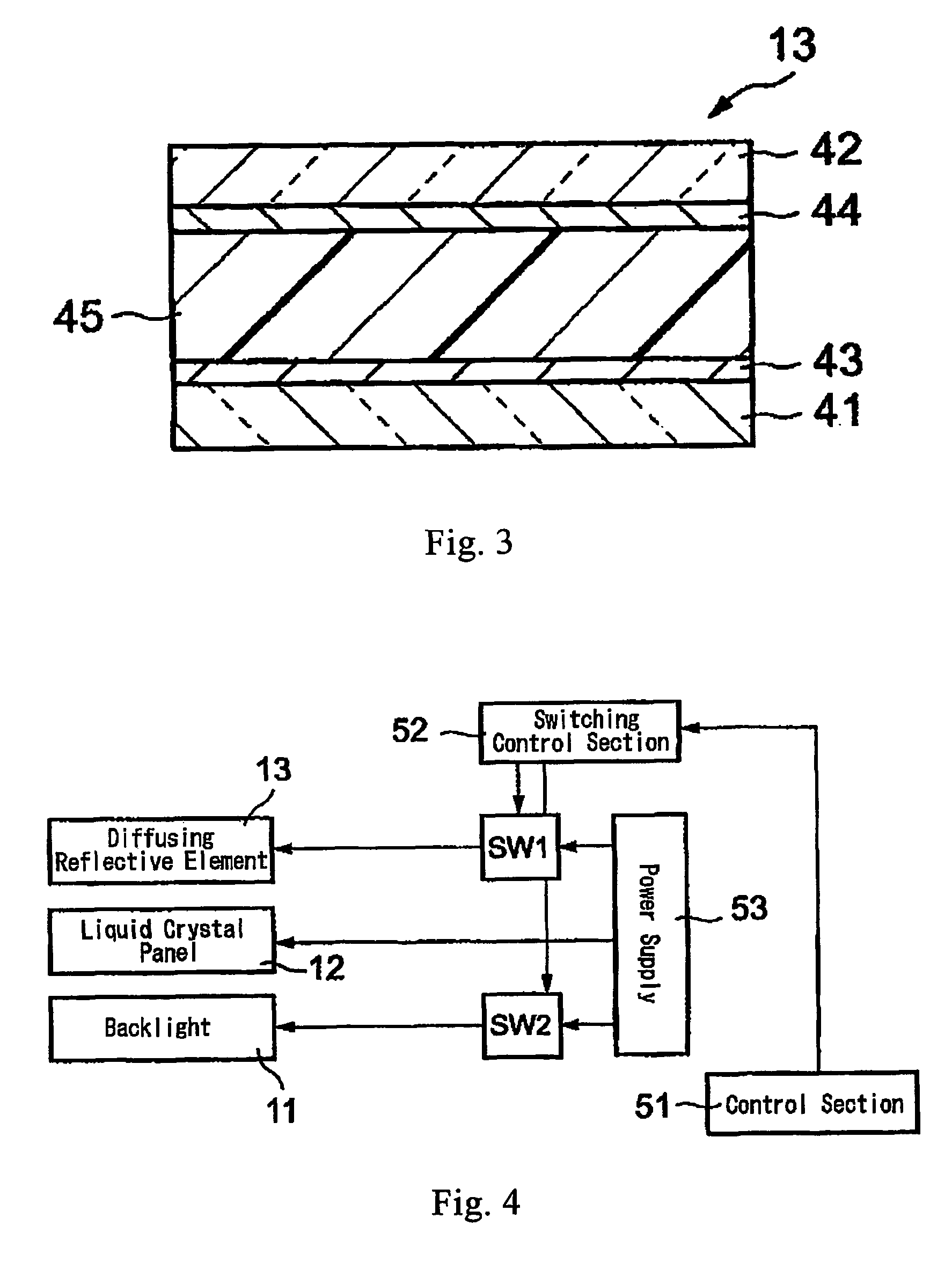
[0051]A diffusing optical element 13 is arranged on the other principal surface of a glass substrate 22 of a liquid crystal panel 61 shown in FIG. 6, that is, on the principal surface opposite the principal surface on which a color filter 27 is provided. The arrangement of the diffusing optical element 13 is the same as that shown in FIG. 3. A polarizer 31 is arranged on the diffusing optical element 13.

[0052]The operation of the transflective liquid crystal display device according to this embodiment having the above described arrangement ...


PUM

PropertyMeasurementUnit
transparentaaaaaaaaaa
poweraaaaaaaaaa
reflection areaaaaaaaaaaa

Abstract

A transflective liquid crystal display device with a reflective mode using external light and a transmissive mode using a light source comprising a light source (11) used in the transmissive mode, a liquid crystal panel (12), arranged over the light source, for operating as display element and a diffusing optical element (13), arranged over the liquid crystal panel, for having a scattering state in the reflective mode and having a non-scattering state in the transmissive mode.

Description

BACKGROUND OF THE INVENTION[0001]1. Field of the Invention[0002]The present invention relates to a transflective liquid crystal display device, particularly to a transflective liquid crystal display device for preventing interferences caused by reflecting light in a reflective mode and for improving contrast in a transmissive mode.[0003]2. Description of Related Art[0004]A so-called transflective liquid crystal display device, which reflects external light incident from the front side, guides it to the front side and at the same time allows incident light from a backlight system on the back to pass and guides it to the same front side, is entering into a full-fledged commercial stage. This type of liquid crystal display device provides effective image displays using principally external light (ambient light) when an environment in which it is used is bright (reflective mode) and principally self-emitted light from the backlight system when the environment is dark (transmissive mode)...

Claims


Application Information

Patent Timeline
Patent Type & Authority Patents(United States)
IPC IPC(8): G02F1/1335G02F1/1334G02F1/13357G02F1/1347
CPCG02F1/13476G02F1/1334G02F2203/09G02F1/133504G02F1/1335G02F1/133
Inventor UKAWA, YUSEI
Owner INNOLUX CORP
Why Eureka
Try Eureka