Liquid crystal display controller and liquid crystal display device

a liquid crystal display controller and display device technology, applied in the direction of instruments, computing, electric digital data processing, etc., can solve the problems of poor display contrast, inability to obtain favorable display contrast under unchanged drive condition, and insufficient reduction of electric power consumption, so as to reduce the number of terminals, reduce the cost of the liquid crystal display controller, and reduce the effect of boosting voltage outpu

Inactive Publication Date: 2007-03-08
SYNAPTICS JAPAN GK
View PDF19 Cites 6 Cited by
  • Summary
  • Abstract
  • Description
  • Claims
  • Application Information

AI Technical Summary

Benefits of technology

[0010] It is an object of the present invention to provide a liquid crystal display controller mounted in an electronic device, wherein the duty for driving the liquid crystal is dynamically changed depending upon the operation state of the system in order to decrease a total amount of electric power consumed by the system, and, when a variable duty display is made, an optimum liquid crystal drive voltage and an optimum liquid crystal drive bias condition are easily set depending upon the duty for driving liquid crystal.
[0012] A further object of the present invention is to provide a liquid crystal display controller capable of producing a display that is most easily viewed depending upon the operation state of the system and a system using the above liquid crystal display controller.
[0018] Moreover, the liquid crystal display controller is provided with a boosting circuit capable of changing the boosting power as desired. The boosting power of the boosting circuit is controlled by a boosting power selection register provided in the liquid crystal display controller. When the liquid crystal display panel is changed from the whole surface display to the display of a portion thereof only, a preset value of the boosting power selection register is dynamically changed by the microprocessor, so that the boosted voltage outputted from the boosting circuit is lowered. The boosting circuit has only one output terminal contributing to decreasing the number of terminals of the liquid crystal display controller and, hence, to decreasing the cost of the liquid crystal display controller.
[0019] By using the above-mentioned means, only part of the rows on the liquid crystal display panel can be selectively driven (at a low duty) by the instruction by the microprocessor, making it possible to lower the operating frequency of the common shift register and the voltage for driving the liquid crystal. This makes it possible to suppress a total amount of electric power consumed by the liquid crystal display controller. Moreover, owing to the provision of a drive bias selection register, an optimum drive bias can be changed with a change in the drive duty, making it possible to prevent the contrast from lowering. When the liquid crystal display panel is driven at a low duty, furthermore, the boosting power of the boosting circuit can be set at a low value in accordance with a preset value of the boosting power-selection register, lowering the boosted voltage to a minimum required limit. This makes it possible to lower the operation voltage of the liquid crystal drive power supply circuit, improving the efficiency of the boosting circuit and, hence, further suppressing the electric current consumed by the liquid crystal display controller.
[0020] Desirably, furthermore, a centering display instruction register is provided in the liquid crystal display controller. The preset value of the centering display instruction register is selectively set by the microprocessor. This makes it possible to display dot-matrix characters at a position easiest to view, e.g., at the central portion of the liquid crystal display panel in the stand-by state of the system such as a portable telephone set. In the case of, for example, a liquid crystal panel capable of displaying dot-matrix characters on 4 rows, the display can be controlled so as to display only on the second row from the above, only on the second and third rows from the above, etc. When the display is produced only on the second row from the above or only on the second and third rows from the above, corresponding common signal lines are driven at a selection level. For the rows (non-display rows) that are not selected as display rows, the common signal lines are driven at a non-selection level. In this case, the preset value of the centering display instruction register and the preset value of the drive duty selection register are fed to the shift control circuit (see FIG. 9) of the common shift register, and a plurality of specified flip-flops are selected in the common shift register.

Problems solved by technology

That is, even the common electrodes of lines that are not displayed are scanned, too, involving a problem that the consumption of electric power cannot be reduced to a sufficient degree during the wait time.
However, a change in the voltage for driving the liquid crystal results in a change in the optimum drive bias ratio, making it impossible to obtain a favorable display contrast Under the unchanged drive condition.
Besides, if only the duty for driving the liquid crystal is simply lowered, then, the display position of the character font is fixed to the uppermost row, causing a problem of poor balance of view from the standpoint of display.

Method used


Image

  • Liquid crystal display controller and liquid crystal display device
  • Liquid crystal display controller and liquid crystal display device
  • Liquid crystal display controller and liquid crystal display device

Examples


Embodiment Construction

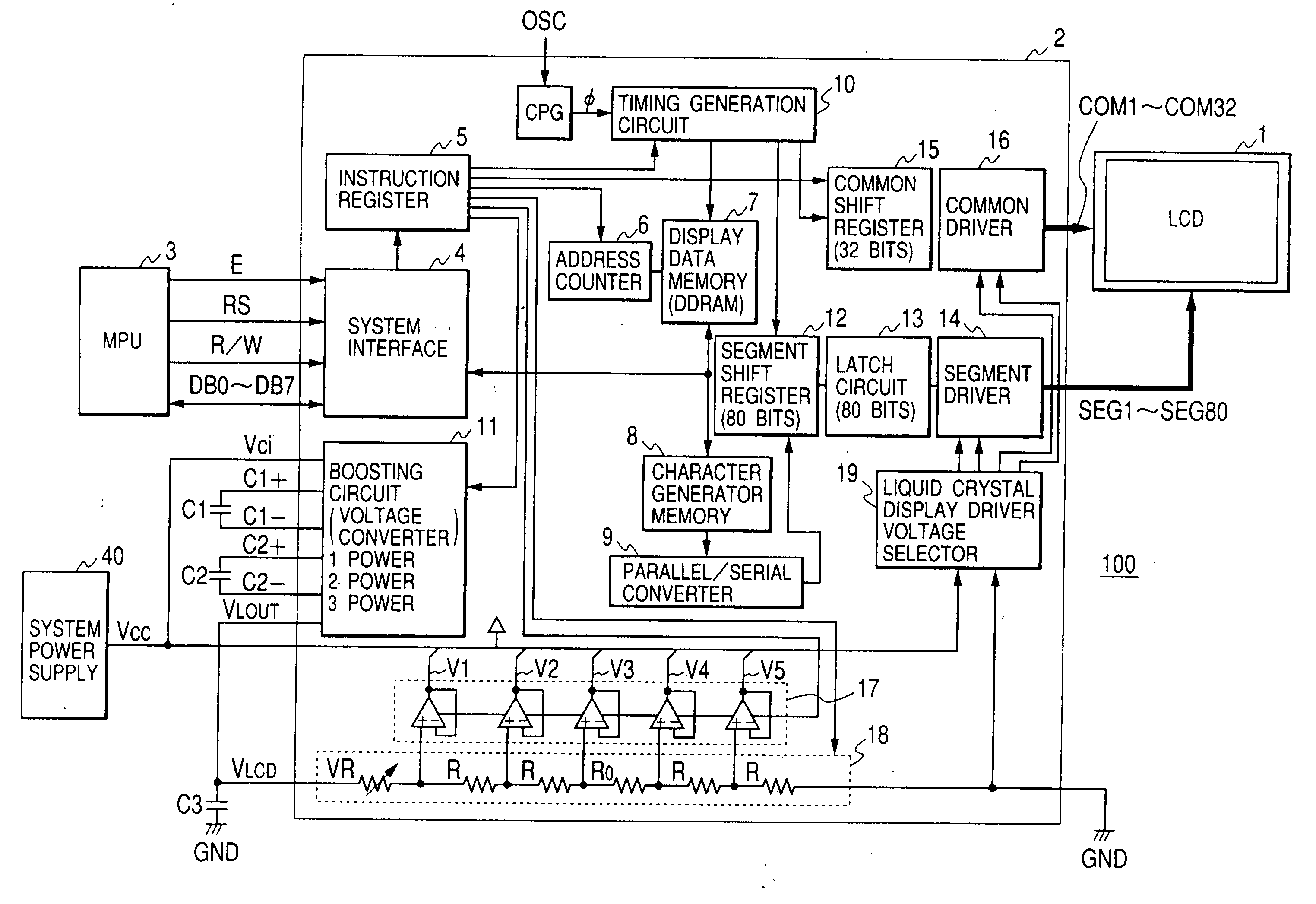
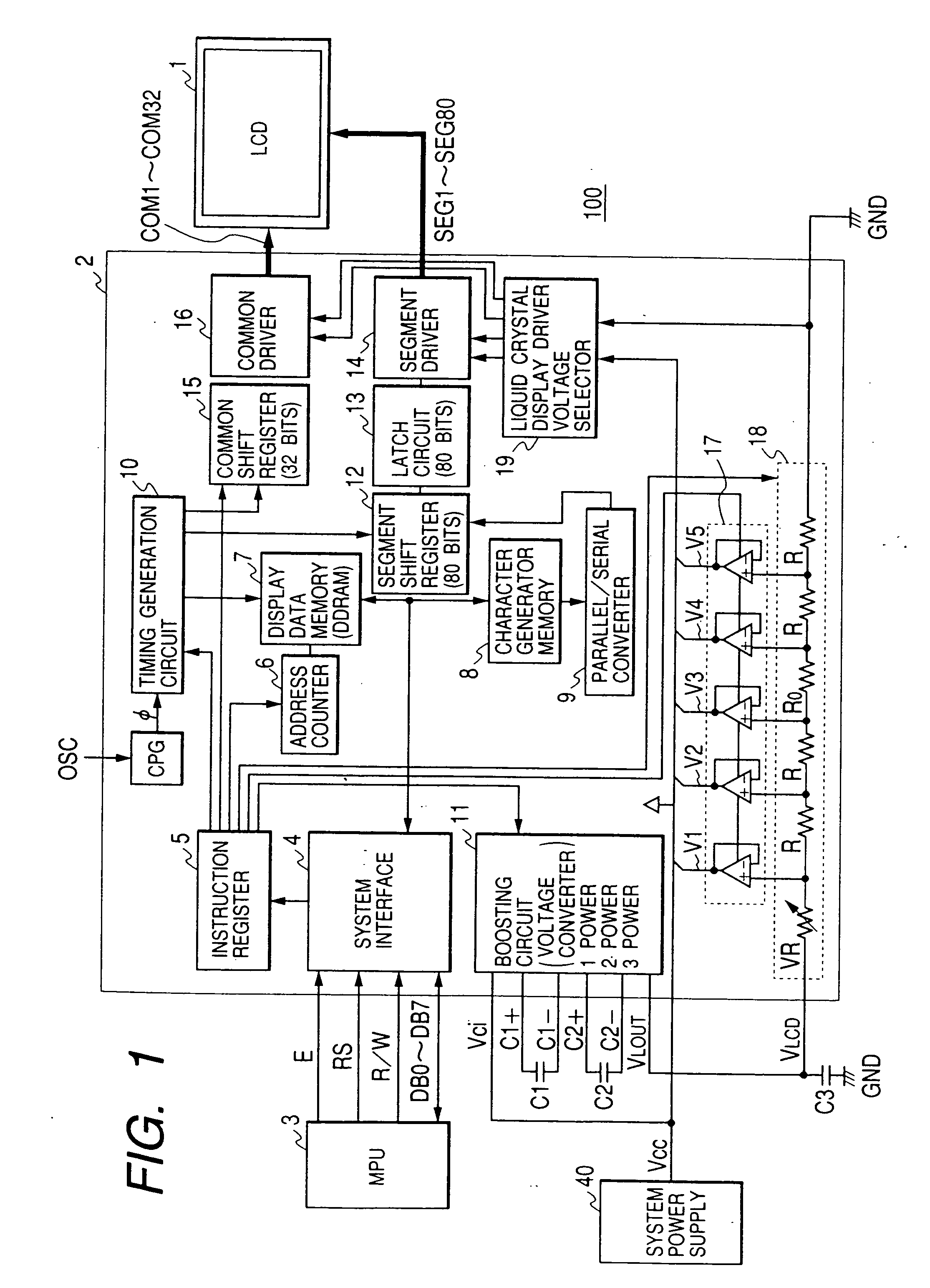
[0049]FIG. 1 shows a liquid crystal display system (liquid crystal display device) 100 of an embodiment according to the present invention. The display system 100 includes a liquid crystal display panel 1 of dot-matrix type, a liquid crystal display controller 2 that outputs signals for driving common electrodes and segment electrodes of the liquid crystal display panel (or liquid crystal display: LCD) to produce a display, a microprocessor (MPU) 3 that sets control data in the liquid crystal display controller 2 and writes display data, and a system power supply 40 such as a battery. Between the microprocessor 3 and the liquid crystal display controller 2 are provided control signal lines for transmitting an enable signal E for activating the controller chip 2, a reset signal RS for instructing a reset, and a read / write control signal R / W from the MPU 3 to the controller 2, and a data bus for transferring data signals DBO to DB7 of 8 bits between the MPU 3 and the controller 2. The...


PUM

PropertyMeasurementUnit
capacitancesaaaaaaaaaa
voltage Vciaaaaaaaaaa

Abstract

In conventional liquid crystal display controllers such as for portable telephone sets, the display is reduced in the stand-by state but the liquid crystal display duty is not changed, i.e., even the common electrodes of the rows that are not producing display are scanned, and the consumption of electric power is not decreased to a sufficient degree in the stand-by state. A liquid crystal display controller (2) includes a drive duty selection register (34) capable of being rewritten by a microprocessor (1), and a drive bias selection register (32). When the display is changed from the whole display on a liquid crystal display panel (3) to a partial display on part of the rows only, the preset values of the drive duty selection register and of the drive bias selection register are changed, so that the display is selectively produced on a portion of the liquid crystal display panel at a low voltage with a low-duty drive.

Description

BACKGROUND OF THE INVENTION [0001] The present invention relates to technology for controlling display and, specifically, to technology that can be particularly effectively adapted to controlling the drive of liquid crystal, such as technology that can be effectively utilized in a display control circuit in a dot-matrix liquid crystal panel for displaying characters or in a liquid crystal panel having a function of displaying pictures, marks, icons, characters (figures), etc. independently of the dot-matrix character display. [0002] A liquid crystal display device, in general, comprises a liquid crystal display panel, a liquid crystal display controller formed as an integrated circuit on a semiconductor substrate for driving the liquid crystal display panel, and a microprocessor (MPU) or a microcontroller including a microprocessing unit (CPU) for controlling the writing of display data or the display operation of the liquid crystal display controller. [0003] A liquid crystal displa...

Claims


Application Information

Patent Timeline
Patent Type & Authority Applications(United States)
IPC IPC(8): G09G3/36G02F1/133G09G3/20
CPCG09G3/2096G09G3/36G09G3/3622G09G3/3644G09G3/3674G09G3/3681G09G3/3696G09G5/22G09G5/222G09G2300/0426G09G2310/0213G09G2310/0232G09G2310/0278G09G2310/04G09G2320/066G09G2320/08G09G2330/02G09G2330/021G09G2330/022G09G2330/023G09G2340/0414G09G2340/0485G09G3/3611
Inventor YOKOTA, YOSHIKAZUTANI, KUNIHIKOSAKAMAKI, GOROUYAMAMOTO, KATSUHIKOYONEOKA, TAKASHIHIGUCHI, KAZUHISASUGIYAMA, KIMIHIKO
Owner SYNAPTICS JAPAN GK
Why Eureka
Try Eureka