Method of low latency interlace to progressive video format conversion

a technology of progressive video and interlace, which is applied in the direction of signal generators with optical-mechanical scanning, picture reproducers using projection devices, television systems, etc., can solve the problems of poor display to the viewer, degrade the resulting frame image, and interlaced images may exhibit distorting artifacts, etc., and achieve the effect of efficiently determining whether an interpolated pixel is presen

Inactive Publication Date: 2008-09-09
PANASONIC CORP
View PDF30 Cites 50 Cited by
  • Summary
  • Abstract
  • Description
  • Claims
  • Application Information

AI Technical Summary

Benefits of technology

[0013]Another feature of the present invention is the use of predetermined filters representing sele...

Problems solved by technology

Interlaced images may exhibit distorting artifacts such as line flicker or loss of vertical detail that degrade the resulting frame image.
For pixels which lie on an edge, this could result in “jaggies” (a line which appears to be jagged or stair-stepped, rather than smooth).
For pixels which are not on an edge, such duplication could result in pixels that do not correspond to the image being displayed, resulting in a poor display to the viewer.
This method also reduces the vertical resolution of the image compared to an interlace-scan image and may result in areas of the image flickering at a 30 Hz rate.
While this method tends to reduce the visibility of the jaggies, it also reduces the vertic...

Method used


Image

  • Method of low latency interlace to progressive video format conversion
  • Method of low latency interlace to progressive video format conversion
  • Method of low latency interlace to progressive video format conversion

Examples


Embodiment Construction

[0027]The present invention relates to a method of converting an interlace scan video signal into a progressive scan video signal, and specifically for generating picture elements (pixels) of interstitial lines in an interlaced field image by simultaneously calculating intermediate pixel values in parallel, utilizing various interpolation methods, and generating an output pixel value based on these intermediate values as well as various flags indicating the presence and degree of motion within the image to be displayed.

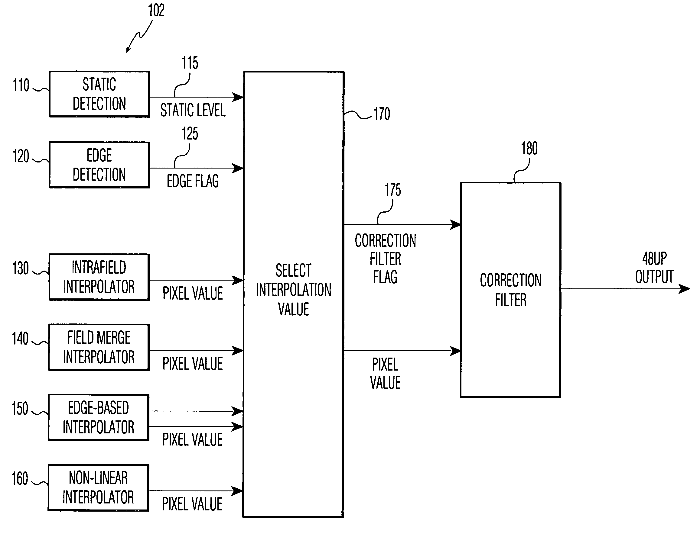
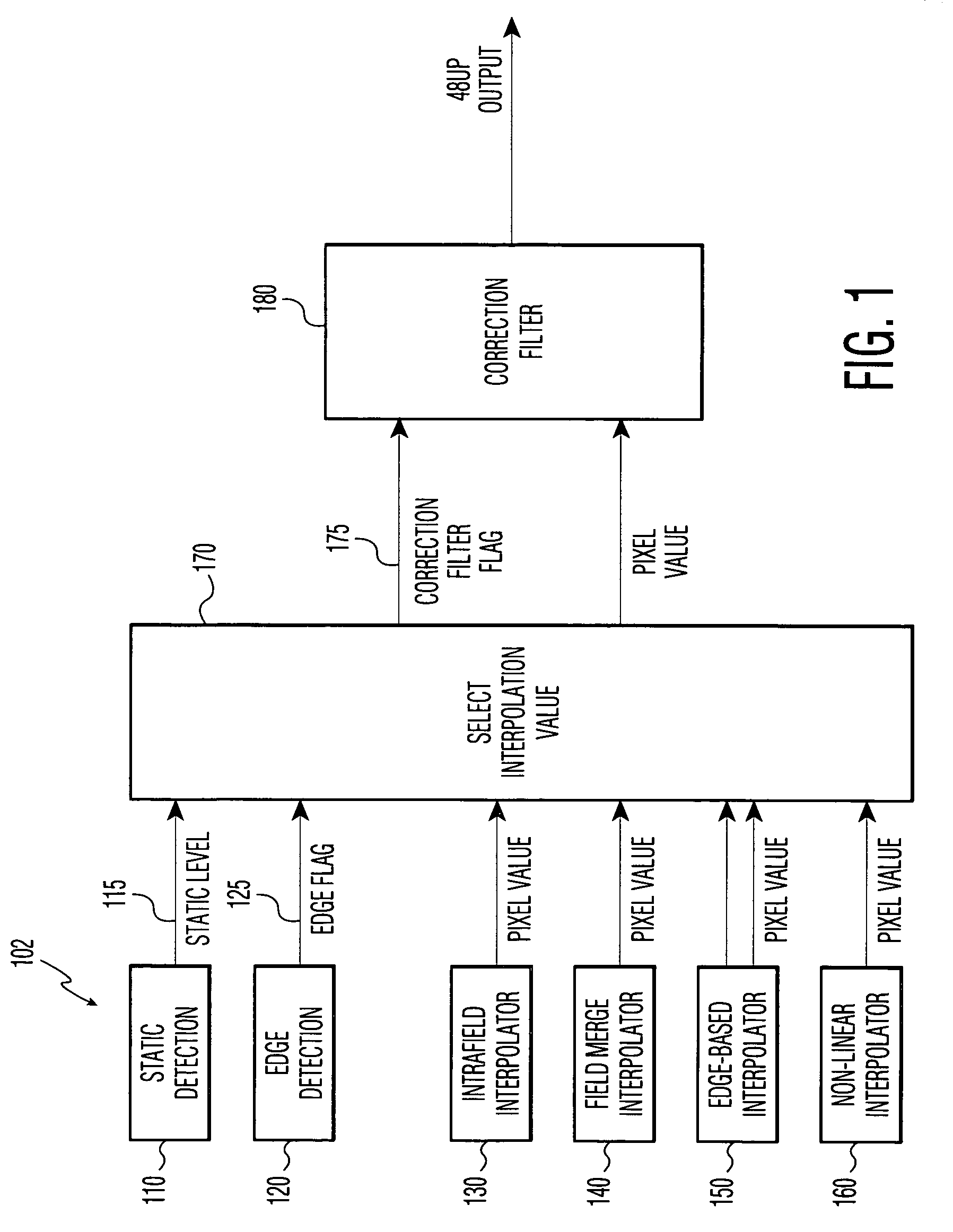
[0028]FIG. 1, shows a system for converting an interlace scan system to a progressive scan system. This system works in successive stages, each of which processes the image in parallel. The stages are: an image processing stage 102, an interpolation selection stage 170 and a filtering stage 180. The image processing stage 102 includes a static detection block 110, an edge detection block 120, an intra-field interpolator 130, an optional field merge interpolator 140, a...


PUM


Abstract

The invention includes a method for converting from an interlace scan image to a progressive scan image. Interpolated rows of pixels, lying between successive rows of the interlace scan image, are generated based upon the received interlace scan rows. The method determines a degree of movement, if any, in the region of a target pixel, and whether a target pixel lies on an edge between visually distinct regions. Multiple potential interpolated values for the target pixel are generated by several interpolation methods, including edge interpolation, inter-field interpolation, non-linear interpolation, and intra-field interpolation. The system uses the degree of movement and edge detection to select or combine one or more of the potential values for the target pixel. At least one correction filter is applied to the result, to correct errors caused by electrical noise in the interlace scan image.

Description

TECHNICAL FIELD[0001]The present invention relates, in general, to interlace to progressive scan conversion systems and, more specifically, to a robust, low-latency method of converting an interlace scan system for a television image to a progressive scan system.BACKGROUND OF THE INVENTION[0002]The image on a television screen consists of picture elements (pixels), arranged horizontally in rows, generally offset vertically by one pixel position from one another. Each pixel is assigned a value which indicates, for a color image, the intensity of the red, green, or blue components of the pixel. A video image is generated by sequentially displaying the rows of pixels as horizontal lines of the image.[0003]Existing analog broadcast standards such as NTSC, PAL and SECAM use two interlaced video fields to generate a single video frame. Each field includes one-half of the horizontal lines that make up the image frame. One field includes all of the odd numbered lines of the frame and the ot...

Claims


Application Information

Patent Timeline
IPC IPC(8): H04N11/20H04N7/01H04N5/44
CPCH04N7/012
Inventor ORLICK, CHRISTOPHER J.MILLER, SCOTT
Owner PANASONIC CORP
Why Eureka
Try Eureka