
Portable ballistic shield

a ballistic shield and portable technology, applied in shields, protective equipment, armoured vehicles, etc., can solve the problems of lack of provisions necessary to allow law enforcement or military personnel to fire upon targets without significant exposure, heavy and cumbersome, etc., to achieve less able to withstand heavy fire, improve the grade of ballistic blankets, and reduce the effect of absorbing heavy fir

Active Publication Date: 2008-09-16
CARTER KEVIN
View PDF14 Cites 21 Cited by
  • Summary
  • Abstract
  • Description
  • Claims
  • Application Information

AI Technical Summary

Benefits of technology

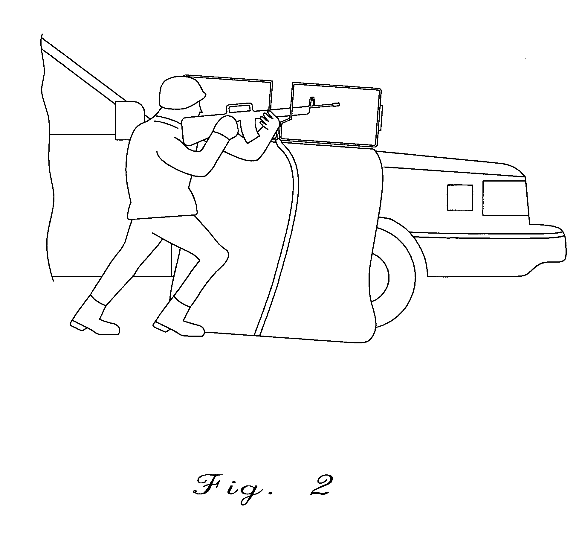
"The present invention is a device for ballistic protection of individual personnel that is portable, versatile, and allows an individual to monitor and aim at a target while retaining cover from return fire. It can be easily attached to existing structures and provides coverage to an individual while allowing them to fire upon a target. The device is made up of a ballistic blanket attached to a bullet resistant polycarbonate member, which can be tailored for different levels of protection. It also includes a dual-panel design that allows the individual to monitor and fire upon a target while in the cover of the device. The invention is easy to set up and provides additional ballistic protection by securing it to existing structures."

Problems solved by technology

Furthermore, these new tactics rely on mobile, forces of individual personnel operating on the ground in close proximity of the target with very little ballistic cover.
Currently, a number of ballistic, protective devices are available and, work well for their intended purposes; however, no known products provide the versatility of the current invention with the incorporation of a rifle stand while still providing complete ballistic protection.
Of course, armor plating has been around for years, but it is heavy and cumbersome and lacks the ability to be used by individuals in mobile tactics.
However, although these devices work well, they lack the provisions necessary to allow law enforcement or military personnel to fire upon a target without significant exposure during the process of aiming and firing.
Thus, current ballistic protection devices fail to provide a portable structure wherein an individual may monitor, aim, and fire upon a target while remaining under the cover of ballistic protection.

Method used


Image

  • Portable ballistic shield
  • Portable ballistic shield
  • Portable ballistic shield

Examples


Embodiment Construction

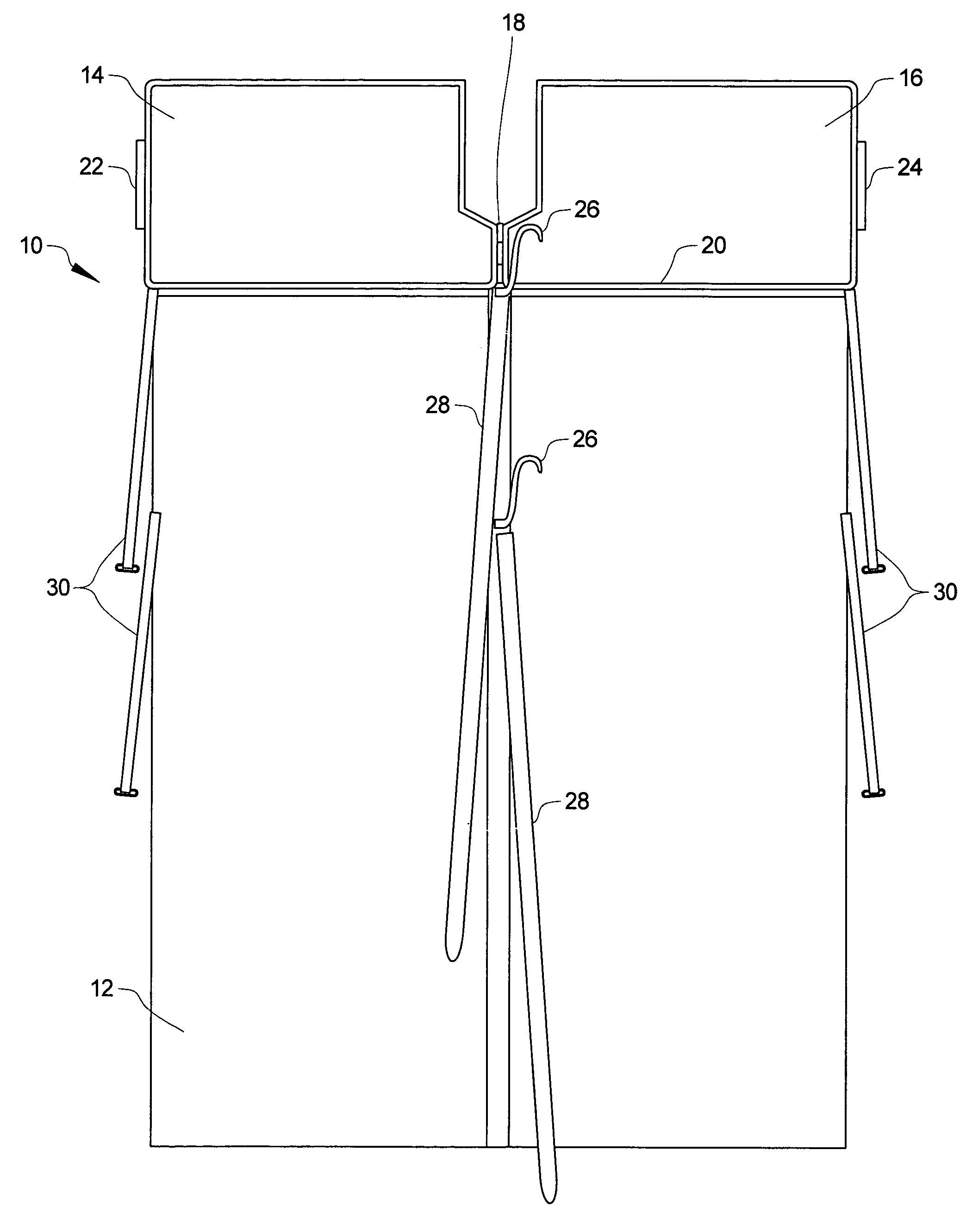
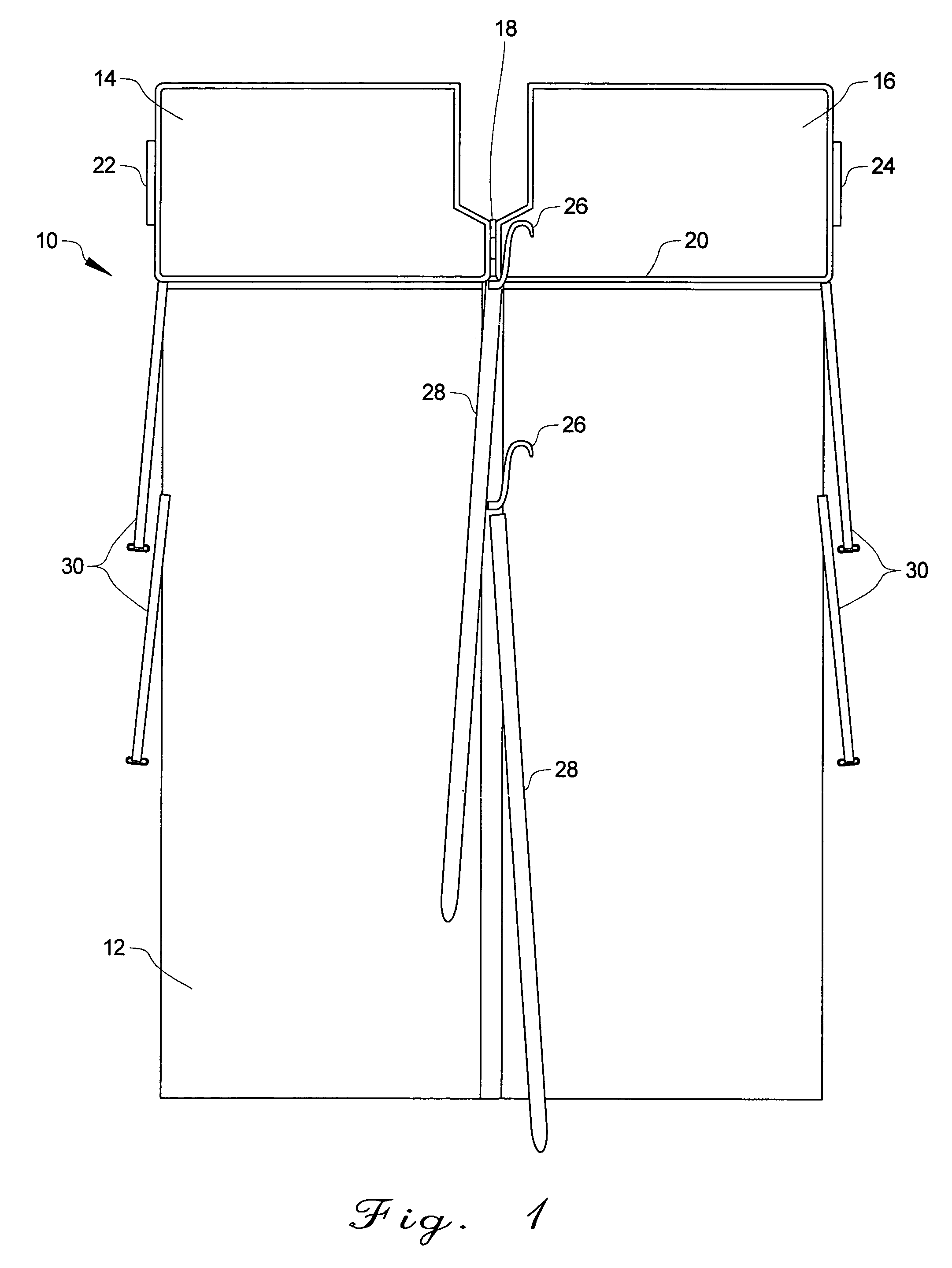
[0023]Referring to FIG. 1, a device for ballistic protection on an individual is shown and is generally designated by numeral 10. Device (10) is comprised of a ballistic blanket member (12). Ballistic blanket member (12) is selected from any one of a number of varying grades of ballistic blankets as known in the art. Ballistic blanket member (12) is selected based on balancing the need for mobility and individual transportability of device (10) versus the need for varying levels of ballistic protection. In other words, the lower the grade of the ballistic protection of ballistic blanket member (12), the lighter and less bulky device (10) is for transportation; however, device (10) would be less able to withstand heavy fire from high caliber weaponry. Conversely, the higher the grade of ballistic blanket member (12), the greater the protection from high caliber fire that device (10) is able to provide, but then device (10) becomes heavier and more bulky to transport and set-up than i...


PUM


Abstract

The present invention is directed toward an apparatus for tactical ballistic protection for an individual. In particular, the present invention provides a portable device for dual use as a ballistic shield and a rifle mounting stand. The invention is comprised on a ballistic blanket attached to dual ballistic resistant transparent panes. The transparent panes are attached via a vertical hinge, at which the attachment point functions as a rifle mounting stand. The invention may be attached to existing structures via a combination of straps and hooks, or the device may be used free standing.

Description

BACKGROUND OF THE INVENTION[0001]1. Field of the Invention[0002]The present invention is directed toward an apparatus for tactical ballistic protection. In particular, the present invention provides a portable device for dual use as a ballistic shield and a rifle mounting stand.[0003]2. Background Information[0004]Police enforcement and military personnel have long desired the ability to safely fire upon a target with relative protection from return fire. To these ends, countless structures have been designed and built in an effort to ensure the appropriate level of protection. These structures range from reinforced buildings to armor plated vehicles as well as numerous variations in between.[0005]However, as police and military tactics have changed, so has their need for ballistic protection. Traditional law enforcement and military tactics traditionally involved outnumbering and overpowering the adversary. However, tactics of both forces have changed to involve much more individua...

Claims


Application Information

Patent Timeline
Patent Type & Authority Patents(United States)
IPC IPC(8): F41H5/08
CPCF41H5/08
Inventor CARTER, KEVIN
Owner CARTER KEVIN
Learn More