Steerable leveraged suspension system suitable for use on a bicycle

a suspension system and leverage technology, applied in the direction of steering devices, frictional roller based transmissions, cycle equipments, etc., can solve the problems of limited travel, no hydraulic damping, and design that does not fully explore the steering geometry in the terms of steering trail, etc., to achieve easy adaptability and higher speed operation

Inactive Publication Date: 2008-09-16
POKRYWKA DAVID FR
View PDF17 Cites 28 Cited by
  • Summary
  • Abstract
  • Description
  • Claims
  • Application Information

AI Technical Summary

Problems solved by technology

However some of these early designs did not fully explore the steering geometry in the terms of steering trail as did later or newer designs have utilized.
In there present day form some are equipped with hydraulic shock absorbers externally mounted, their spring rates are designed for high speed usage and they do not take full advantage of leverage.
This same design found on many makes of bicycles today although with limited Travel and no hydraulic damping.
They are adequate for there intended purpose, but are difficult To fine tune for differences in rider weights and road conditions.
All of the types of steerable suspension systems suitable for use on bicycles today typically do not make use of leverage in an economical and easily tuneable design.

Method used


Image

  • Steerable leveraged suspension system suitable for use on a bicycle
  • Steerable leveraged suspension system suitable for use on a bicycle
  • Steerable leveraged suspension system suitable for use on a bicycle

Examples


Embodiment Construction

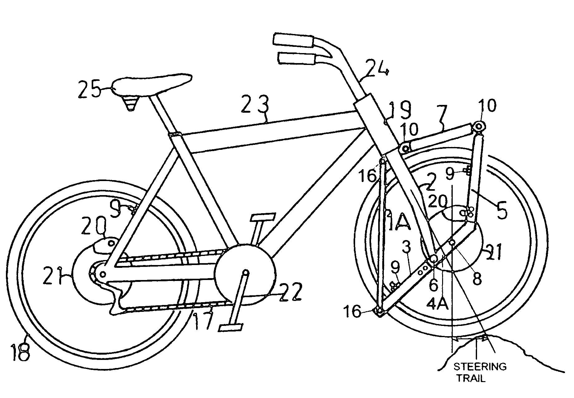
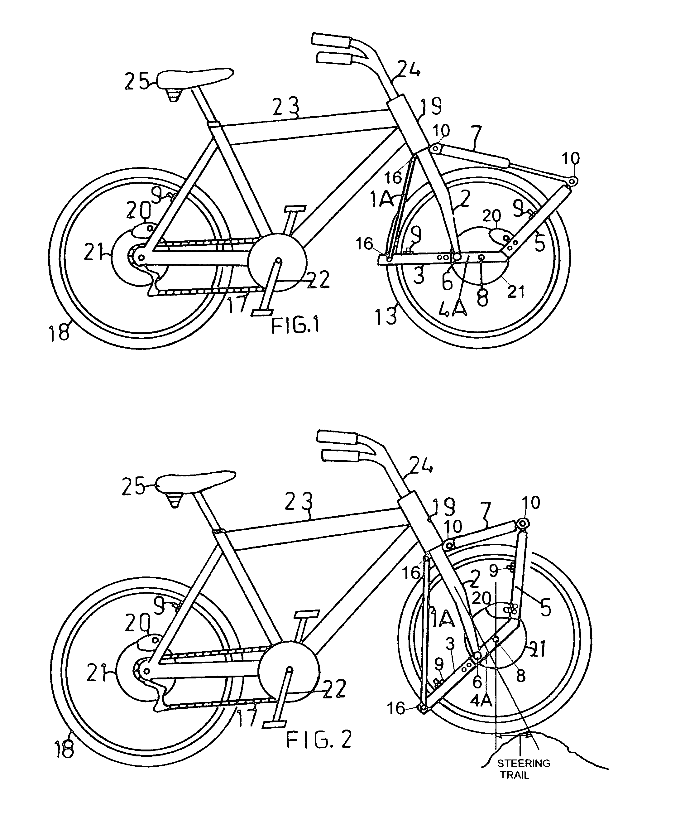
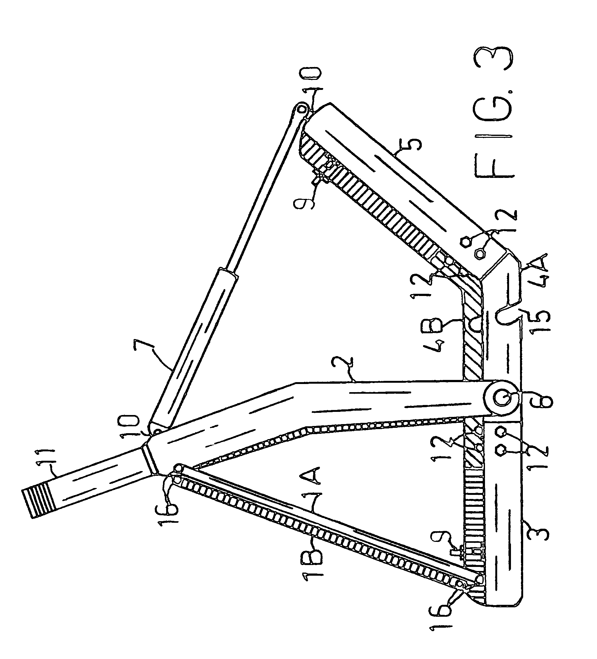
[0016]Referring to the drawings of FIG. 1 thru FIG. 5 illustrates the Steerable Leveraged Suspension system as shown in items 1A thru 16. The illustrations are to provide a means of description and are not intended to limit the scope of the present invention.

[0017]Further descriptions in FIG. 2 to one who has knowledge in the art describes the Steerable Leveraged Suspension system, and to simplify understanding it is attached to a bicycle frame 23 to which is attached a rear wheel 18, also shown is a disc brake system caliper 20 and disc 21, a seat 25 crank peddles 22 a chain or toothed belt 17 and handlebars 24.

[0018]The Steerable Leveraged Suspension system items 1 a thru 16 as viewed in FIG. 2 can be appreciated by one skilled in the art, is attached to the bicycle frame 23 by means of the bicycle frame neck tube 19, FIG. 2 into which fits the vertical fork neck 11, FIG. 3 thru FIG. 5 in typical bicycle fashion via ball bearings (not shown), for the purpose of steering movement. ...


PUM


Abstract

A steerable leveraged suspension suitable for a bicycle or electric Bicycle of motorized wheel hub design. Comprising of a vertical fork, which attaches to a bicycle frame front neck tube. The lower portion of said vertical fork is curved at its bottom to the rear of the frame neck head tube centerline, so as to improve steering trail geometry. The bottom of the curved fork is a pivot point to which pivot arms are attached. To the pivot arms the front wheel is attached forward of the pivot points by means of slots to which the front wheel Axel shaft fits into. Also two leveraging pivot arm extensions are attached. The leveraging arms provide a means of suspension leverage and a mounting point for brakes. For the purpose of suspension are rubber cord (bungee cord) and a compression damping spring of gas charge type.

Description

BACKGROUND OF INVENTION[0001]The present invention relates to a vehicle steerable suspension system particularly suitable for use on a Bicycle or an Electric powered Bicycle of Motorized Wheel Hub design.[0002]Bicycle suspension systems have been around for well over 100 years going back to the early days of bicycles and continuing on into motorcycles. Some of the first front suspension systems designs being simple and somewhat effective in providing a means of shock absorptions. However some of these early designs did not fully explore the steering geometry in the terms of steering trail as did later or newer designs have utilized.[0003]Many improvements have been made over the years some types have origins beginning with aircraft as with telescopic sliding fork tube type other types have there origins with motorcycles.[0004]Some early designs which have external springs, such as Leading Link or Earls type, Girder type, springer type, to name just a few, some of which are still use...

Claims


Application Information

Patent Timeline
Patent Type & Authority Patents(United States)
IPC IPC(8): B62M1/00
CPCB62K25/18
Inventor POKRYWKA, DAVID FRANK
Owner POKRYWKA DAVID FR
Why Eureka
Try Eureka