Dynamic vehicle grid infrastructure to allow vehicles to sense and respond to traffic conditions

a technology of dynamic vehicle grid and traffic conditions, applied in brake systems, process and machine control, instruments, etc., can solve the problems of difficult for automobile 2, automobile 3 or even more cars behind to detect emergency braking, and no way for drivers to know

Active Publication Date: 2008-09-16
WAYMO LLC
View PDF13 Cites 86 Cited by
  • Summary
  • Abstract
  • Description
  • Claims
  • Application Information

AI Technical Summary

Benefits of technology

[0008]It is an object of the present invention to provide a method and system in which a motor vehicle can warn other motor vehicles in the vicinity of an event occurring with the warning vehicle.
[0010]It is a third objective of the present invention to provide a method and system in which a motor vehicle that receives a signal of an event can relay that signal to other vehicles in the vicinity.
[0011]It is a fourth objective of the present invention to provide a system of sensors and transmitters that can detect an event and transmit a signal indicating that detected event.
[0012]It is a fifth objective of the present invention to provide a system within a motor vehicle that can detect an event with the vehicle, distinguish the type of event that is occurring and transmit a message to other vehicles in the vicinity indicating the type of event that is occurring.

Problems solved by technology

Until the driver has to slow down, there is no way for the driver to know that stationary cars are currently one mile ahead.
This method is very expensive and relies on a system that can detect traffic patterns and problems.
While this method obviously works, it is difficult for an automobile 2, automobile 3 or even more cars behind to detect an emergency braking.
Although these approaches attempt to warn other drivers of potential hazards, there is no solution in place today that can warn a driver of an emergency brake of a vehicle out of sight of the driver.

Method used


Image

  • Dynamic vehicle grid infrastructure to allow vehicles to sense and respond to traffic conditions
  • Dynamic vehicle grid infrastructure to allow vehicles to sense and respond to traffic conditions
  • Dynamic vehicle grid infrastructure to allow vehicles to sense and respond to traffic conditions

Examples


Embodiment Construction

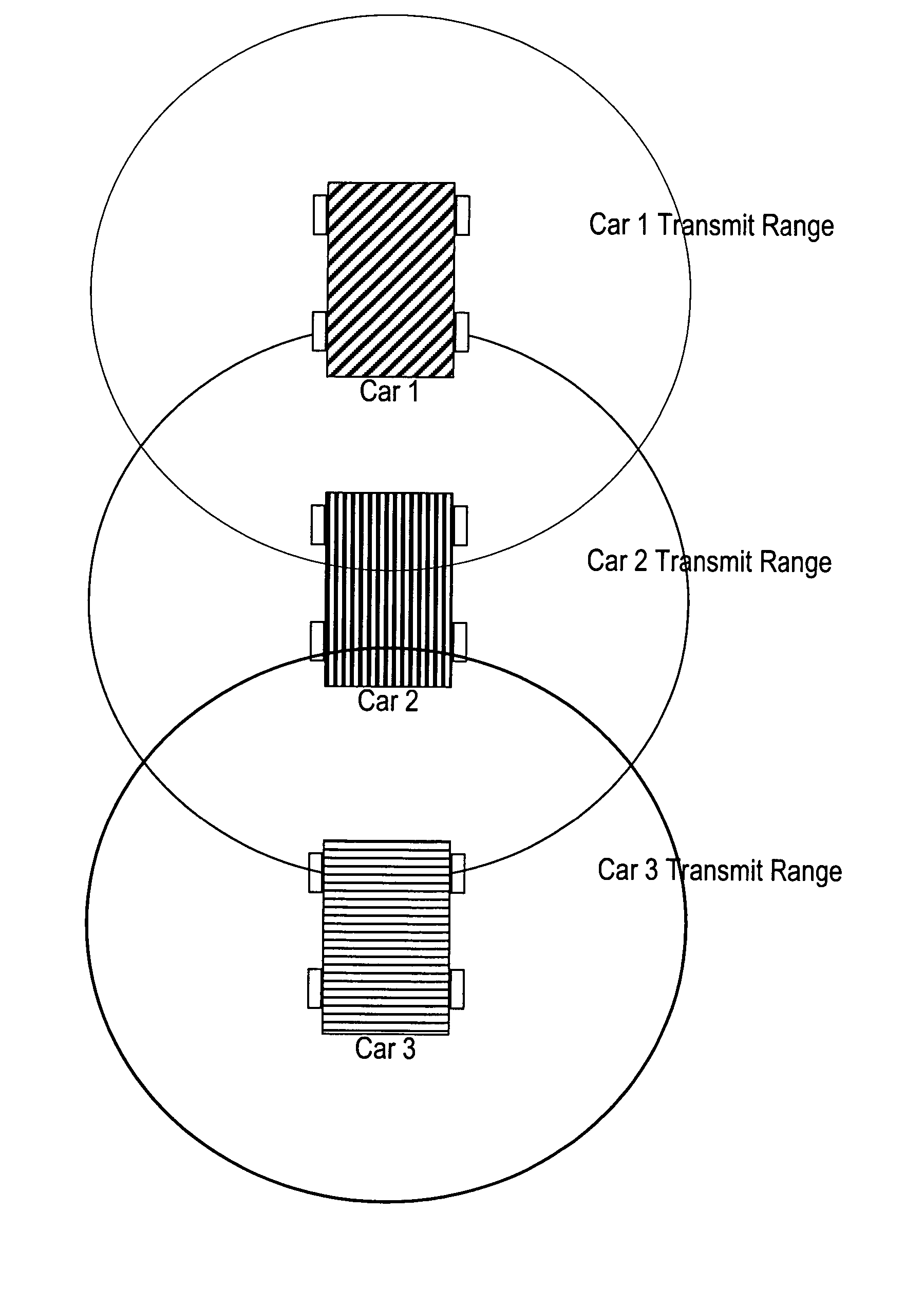
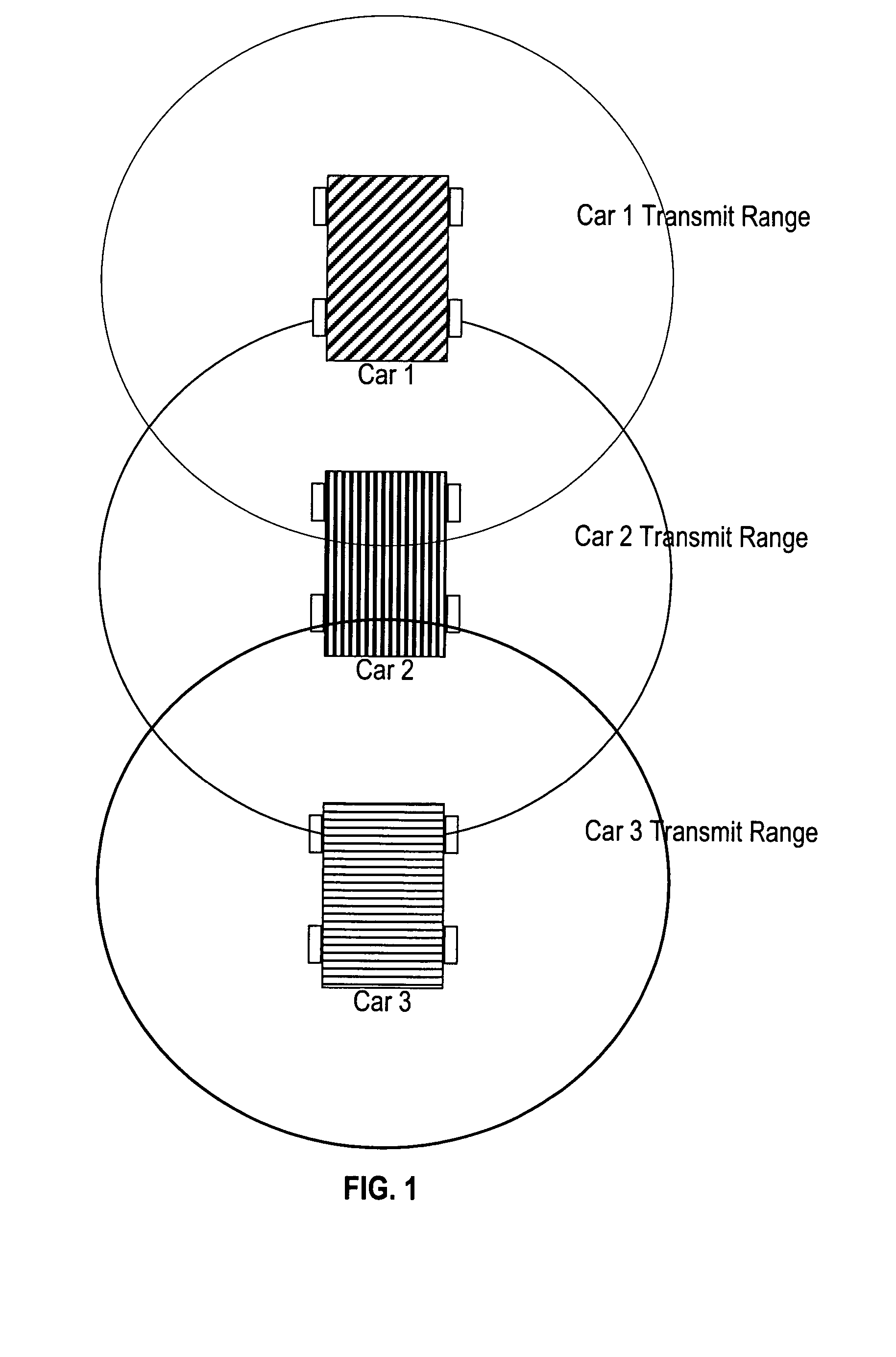
[0020]FIG. 1 illustrates a configuration of a vehicle traffic grid of the present invention. This grid shows three vehicles, cars 1, 2 and 3, that can be traveling on a roadway in close proximity to each other. Each vehicle has transmission range in which the vehicle can reliably transmit signals to and receive signals from other vehicles in the grid. Because of this close proximity, if a vehicle experiences an event such as a sudden turn or the steering wheel or a sudden deceleration resulting braking, signals indicating these events can be transmitted to and received at the other vehicles in the vicinity. When the driver of a vehicle receives the signal, that driver will be alerted to the event and can take responses actions if necessary. In this illustration, car number 2 has a transmission range in which it can send messages to and receive messages from cars 1 and 3.

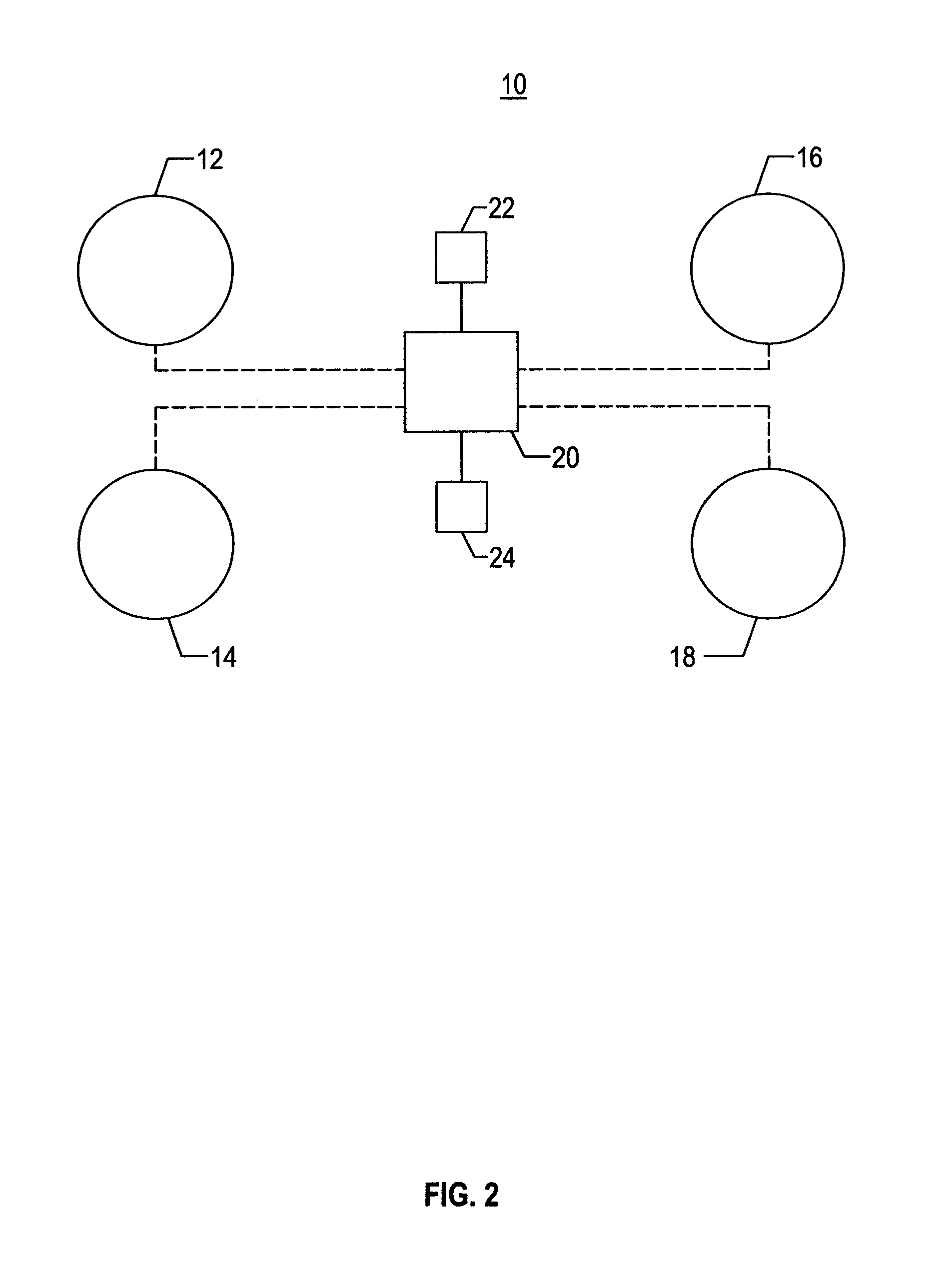
[0021]FIG. 2 illustrates the configuration of vehicle components that are used in the implementation of the presen...


PUM


Abstract

A dynamic ‘vehicle grid’ system provides the ability for drivers to be automatically warned to the conditions of other vehicles in the vicinity. In this grid system, a motor vehicle would be equipped with a transmitter, receiver, computer and a selection of sensors. Other adjacent vehicles are also contain the same of equipment for transmitting and receiving signals. When the sensors in a vehicle detect a change such as hard braking (rapid deceleration) or very slow speed (blockages), it automatically sends this information via the transmitter over a wireless communication channel to any other receivers in the vicinity.

Description

FIELD OF THE INVENTION[0001]The present invention describes a system and method to create a dynamic grid infrastructure made up of multiple automobiles. This grid infrastructure allows traffic and other important information to be propagated between each of the automobiles comprising the infrastructure. The invention describes an algorithm that allows the grid infrastructure to be created and managed, as well as the details of the information that is passed between automobiles that make up the grid.BACKGROUND OF THE INVENTION[0002]In the current art, automobiles and other vehicles have no simple way of communicating with one another. Consider the example where a car has to suddenly brake in front of another car. The driver of the trailing vehicle perhaps sees the brakes of the car in front, cueing him or her to slow down. However, what about the car following behind the second one, or the car behind that car? Consider another example of a line of stationary cars one mile ahead of a ...

Claims


Application Information

Patent Timeline
Patent Type & Authority Patents(United States)
IPC IPC(8): G08G1/00
CPCG08G1/162H04L67/12H04W4/46
Inventor BOSS, GREGORY JENSENDAWSON, CHRISTOPHER JAMESGRAHAM, BARRY MICHAELHAMILTON, II, RICK ALLENWATERS, TIMOTHY MOFFETT
Owner WAYMO LLC
Why Eureka
Try Eureka