Liquid crystal module brightness measurement apparatus and brightness measurement apparatus

a technology of brightness measurement apparatus and liquid crystal module, which is applied in the direction of optical radiation measurement, instruments, spectrometry/spectrophotometry/monochromators, etc., can solve the problems of increasing the cost increasing the setting area of the brightness measurement apparatus, and increasing the size of the device. , to achieve the effect of reducing the increase in the setting area and the cost of the devi

Inactive Publication Date: 2008-09-16
FUNAI ELECTRIC CO LTD
View PDF20 Cites 8 Cited by
  • Summary
  • Abstract
  • Description
  • Claims
  • Application Information

AI Technical Summary

Benefits of technology

[0010]An object of the present invention is to provide a liquid crystal module brightness measurement apparatus and a brightness measurement apparatus which can alleviate increase in the setting area and the cost which tend to increase as the size of the display apparatus such as a liquid crystal display and the like become larger.
[0020]Specifically, by moving the liquid crystal module placed on the first placement unit only in one direction (the shorter side direction of the liquid crystal module) and by moving the measurement unit only in one direction (the longer side direction of the liquid crystal module), the brightness and chromaticity of the entire upper surface of the liquid crystal module placed on the first placement unit can be measured. Therefore, both the liquid crystal module and the measurement unit are moved only in one direction. Thus, increase in the setting area and the cost associated with increase in size of a display apparatus such as a liquid crystal display and the like can be alleviated. Further, since the liquid crystal module placed on the first placement unit is moved along the shorter side direction of the liquid crystal module, when compared with a case where the liquid crystal module placed on the first placement unit is moved along the longer side direction of the liquid crystal module, the liquid crystal module can have a smaller moving range. Thus, increase in the setting area associated with increase in size of a display apparatus such as a liquid crystal display can be alleviated more.
[0021]Furthermore, the placement unit rotating mechanism can rotate the second placement unit about a predetermined axis. Thus, the brightness and chromaticity of the liquid crystal module can be measured not only in a direction orthogonal to the upper surface of the liquid crystal module placed on the second placement unit, but also in a direction oblique to the upper surface of the liquid crystal module. This can provide various measurements. Furthermore, the liquid crystal module placed on the second placement unit rotated only about the predetermined axis along the placement surface of the second placement unit. Thus, increase in the setting area of the brightness measurement apparatus can be alleviated even the second placement unit is provided.
[0028]Specifically, by moving the object placed on the placement unit only in one direction (x-axis direction) and by moving the measurement unit only in one direction (y-axis direction), the brightness or chromaticity of the entire upper surface of the object to be-measured placed on the placement unit can be measured. Therefore, the object to be measured as well as the measurement unit is moved only in one direction. Thus, increase in the setting area and the cost associated with increase in size of a display apparatus can be alleviated.
[0031]In the present invention, the same effect is obtained. Further, the x-axis direction is in the same direction as the shorter side direction of the object to be measured placed on the placement unit. The y-axis direction is in the same direction as the longer side direction of the object to be measured placed on the placement unit. Specifically, the object to be measured placed on the placement unit is moved along the shorter side direction of the object. Therefore, when compared with a case where the object to be measured placed on the placement unit is moved along the longer side direction of the object, the object to be measured can have a smaller moving range. Thus, increase in the setting area associated with increase in size of a display apparatus can be alleviated more.
[0035]In the present invention, the same effect is obtained. Further, the placement unit rotating mechanism can rotate the placement unit about the predetermined axis. Thus, the brightness or chromaticity of the object to be measured can be measured not only in a direction orthogonal to the upper surface of the object placed on the placement unit, but also in a direction oblique to the upper surface of the object, thus providing various measurements. Furthermore, the object to be measured placed on the placement unit is rotated only about the predetermined axis along the placement surface of the placement unit. Thus, increase in the setting area of the brightness measurement apparatus can be alleviated even when the apparatus includes the second placement unit.

Problems solved by technology

Along with the recent trend in liquid crystal displays having a larger size, a problem has been caused where a measurement apparatus for measuring predetermined measurement items for components constituting a liquid crystal display also requires a larger size.
Therefore, there is a problem where as the area of liquid crystal module increases, the setting area for the brightness measurement apparatus increases.
However, in order to realize the above-described measurement unit that can be moved in two directions of the shorter side direction and longer side direction of the liquid crystal module, for example, a part supporting the measurement unit must be stronger, which causes a problem of an increased cost in the brightness measurement apparatus.

Method used


Image

  • Liquid crystal module brightness measurement apparatus and brightness measurement apparatus
  • Liquid crystal module brightness measurement apparatus and brightness measurement apparatus
  • Liquid crystal module brightness measurement apparatus and brightness measurement apparatus

Examples


Embodiment Construction

[0044]Hereinafter, a description is given of an embodiment of the liquid crystal module brightness measurement apparatus (hereinafter referred to as a brightness measurement apparatus) according to the present invention in detail with reference to drawings. The scope of the invention is not limited to the illustrated examples.

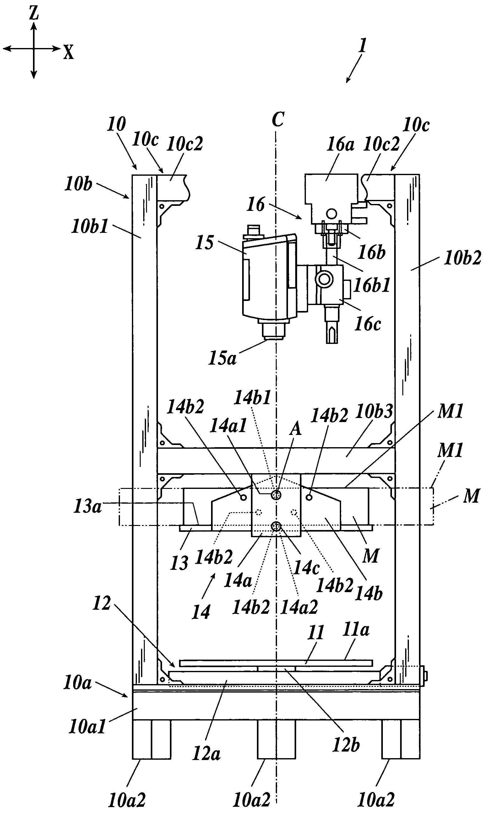
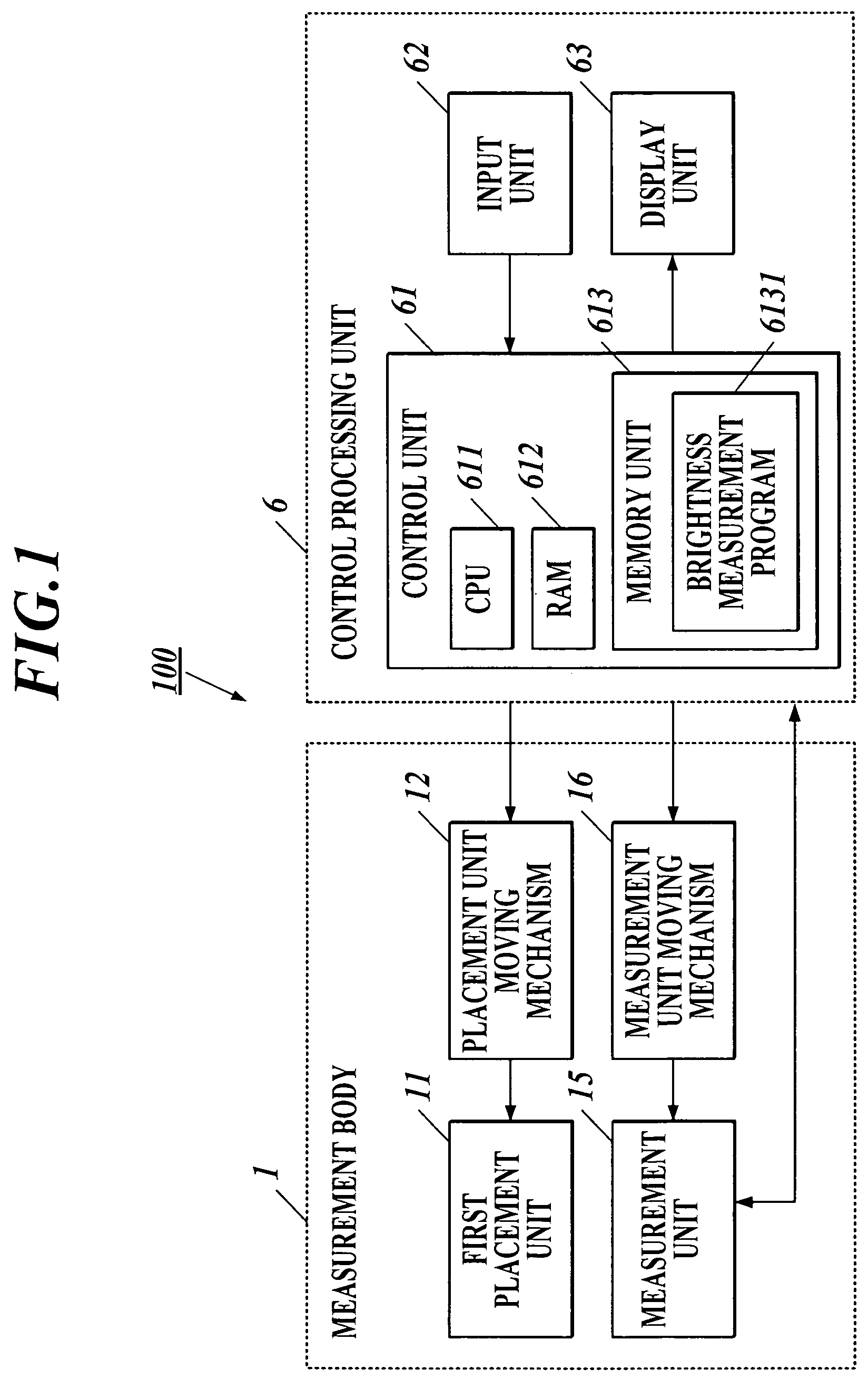
[0045]As shown in FIG. 1, for example, a brightness measurement apparatus 100 comprises a measurement body 1 for measuring the brightness and chromaticity of a liquid crystal module M as an object to be measured, and a control processing unit 6 that controls the measurement body 1 and processes data obtained by the measurement body 1. The measurement body 1 is electrically connected with the control processing unit 6.

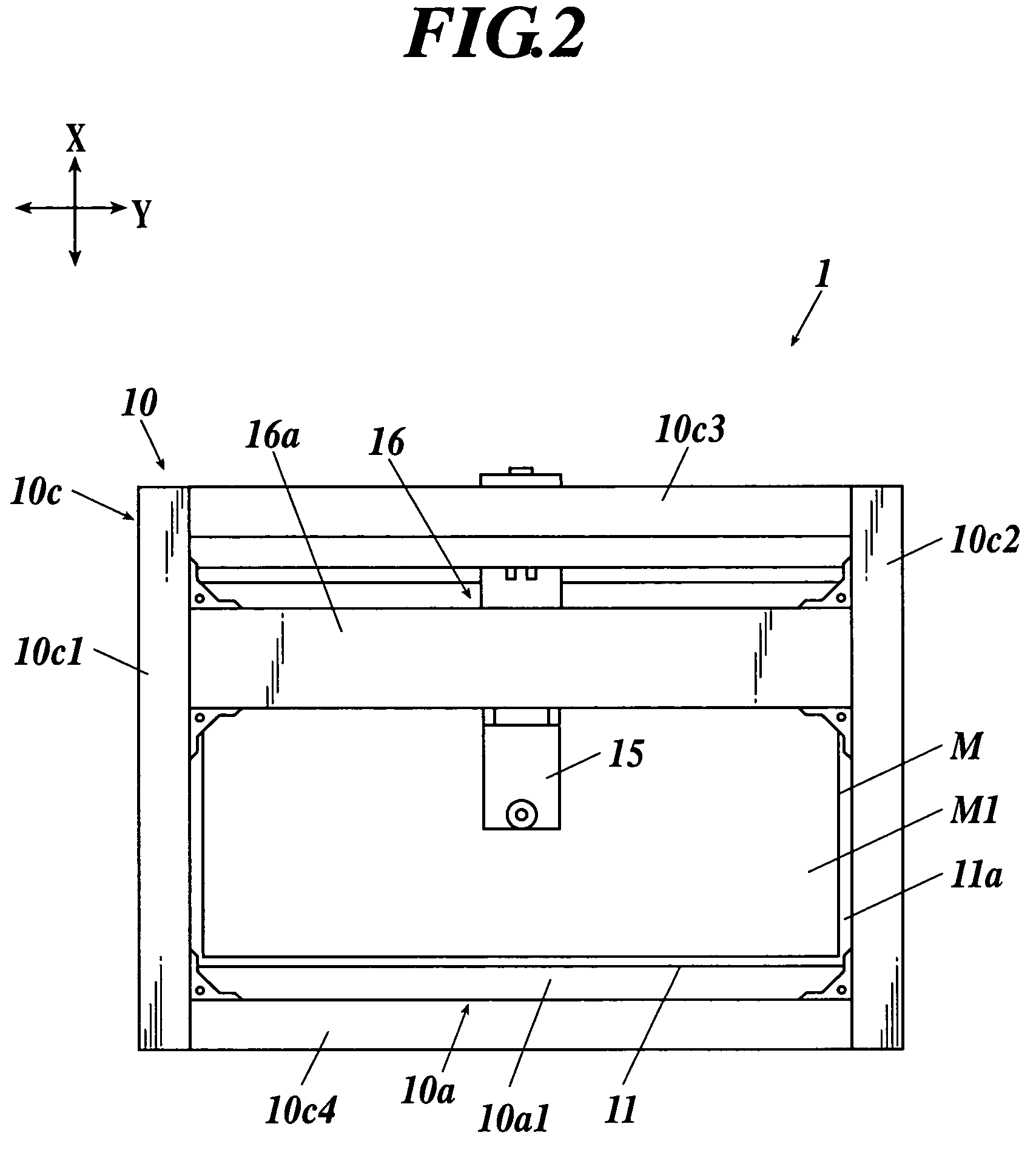
[0046]First, as shown in FIG. 2, for example, the shorter side direction of the upper surface of the measurement body 1 is assumed as an x-axis direction, and the longer side direction of the upper surface of the measurement body 1 is assumed as a ...


PUM

PropertyMeasurementUnit
brightnessaaaaaaaaaa
brightness measurementaaaaaaaaaa
sizeaaaaaaaaaa

Abstract

A brightness measurement apparatus which includes a placement unit on which an object to be measured is placed, a measurement unit for measuring brightness or chromaticity from an upper surface of the object placed on the placement unit, a placement unit moving mechanism for moving the placement unit in an x-axis direction, and a measurement unit moving mechanism for moving the measurement unit in a y-axis direction orthogonal to the x-axis direction.

Description

BACKGROUND OF THE INVENTION[0001]1. Field of the Invention[0002]The present invention relates to a liquid crystal module brightness measurement apparatus and a brightness measurement apparatus.[0003]2. Description of the Related Art[0004]Conventionally, a brightness measurement apparatus for measuring the brightness, chromaticity, and the like of a liquid crystal module has been known for the purpose of, for example, the quality inspection and quality control of a liquid crystal module constituting a liquid crystal display.[0005]Specifically, the brightness measurement apparatus comprises, for example, a placement unit on which a liquid crystal module is placed, and a measurement unit for measuring the brightness, chromaticity, and the like from an upper surface (display surface) of the liquid crystal module placed on the placement unit. The brightness measurement apparatus as described above is designed so that, for example, the position of the measurement unit is fixed and the pla...

Claims


Application Information

Patent Timeline
Patent Type & Authority Patents(United States)
IPC IPC(8): G01J1/42B23K26/38G01B7/00G01J1/02G01M11/00G02F1/13G02F1/1333
CPCG01J1/04G02F1/1309G01J3/02G01J1/0223G01J1/0403
Inventor OKA, MASAHARU
Owner FUNAI ELECTRIC CO LTD
Why Eureka
Try Eureka