
Dynamic sliding module and uses thereof

a technology of sliding module and sliding module, which is applied in the direction of coupling device connection, electrical apparatus casing/cabinet/drawer, engagement/disengagement of coupling parts, etc., can solve the problems of limited surface area of keyboard and display on a mobile phone, and difficulty in integrating all the foregoing functions into such a small mobile phone. , to achieve the effect of increasing the area of the exposable surface, increasing the sliding reliability of the sliding electronic module, and increasing the expo

Inactive Publication Date: 2008-09-16
HTC CORP
View PDF3 Cites 13 Cited by
  • Summary
  • Abstract
  • Description
  • Claims
  • Application Information

AI Technical Summary

Benefits of technology

[0007]It is an objective of the present invention to provide a dynamic sliding module to increase the surface area of an electronic device.
[0008]It is another objective of the present invention to provide a dynamic sliding module using an attracting force, such as a magnetic force, to engage a dynamic slide with a track in a part of the stroke thereof to increase the sliding stability for two electronic sliding modules of an electronic device.
[0009]It is yet another objective of the present invention to provide a dynamic sliding module with a dynamic slide escaping from a track in a part of the stroke thereof to increase the surface area and the stroke of two electronic sliding modules of an electronic device.
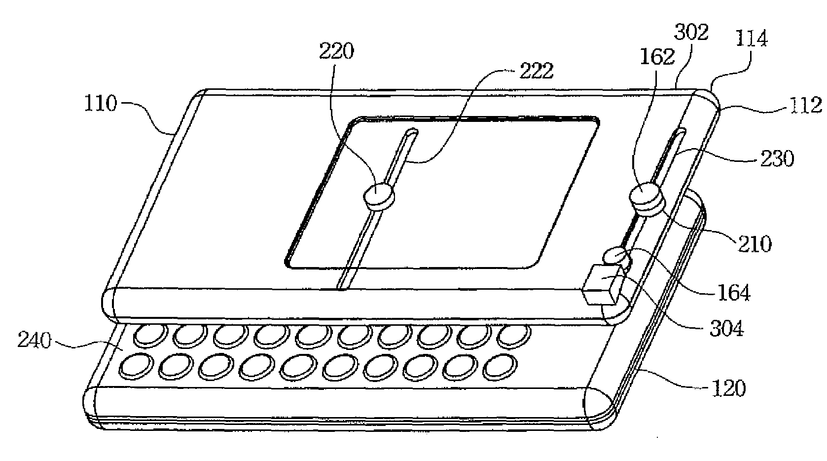
[0010]To accomplish the above objectives, the present invention provides a dynamic sliding module for coupling a first electronic module to a second electronic module of an electronic device, and increasing both the sliding reliability and the area of exposable surfaces therebetween. The electronic device is, for example, a mobile phone, such as a slider cell phone. The first electronic module is, for example, a sliding display, and the second electronic module is, for example, a sliding keyboard. The dynamic sliding module includes a track with a first opening, a dynamic slide, and a guiding device, such as an attracting device, to guide the dynamic slide into the track through the first opening while the dynamic slide is moved to be aligned with the first opening so as to enable the dynamic slide to engage with and slide on the track.
[0014]The dynamic sliding module can further utilize a first slide attached on the track to couple the first electronic module to the second electronic module. The diameter of the first slide is preferably larger than the diameter of the dynamic slide. More preferably, the diameter of the first slide is larger than the diameter of the first opening and / or the second opening so that the first slide can slide on the track and be prevented from escaping the track. The first slide is preferably lower than the wedge-shaped block to prevent the first slide from touching the wedge-shaped block while the dynamic slide is pushed out of the track to further increase the area of the exposable surface between the first electronic module and the second electronic module. Alternatively, the wedge-shaped block is designed to be a stopping block for stopping the first slide.
[0015]Accordingly, the dynamic sliding module according to the present invention can increase the sliding reliability of the sliding electronic modules for the electronic device, and increase the area of the exposable surfaces for the electronic device to control the electronic device and / or increase the functionality thereof. In addition, since the dynamic slide only engages with the track in a part route of the track, the dynamic sliding module can increase the variations of the electronic device, especially for the mobile phone.

Problems solved by technology

Therefore, the surface area for the keyboard and display on a mobile phone is limited.
Integrating all the foregoing functions into such a small mobile phone is difficult.

Method used


Image

  • Dynamic sliding module and uses thereof
  • Dynamic sliding module and uses thereof
  • Dynamic sliding module and uses thereof

Examples


Embodiment Construction

[0020]The following description is currently the best implementation of the present invention. This description is not to be taken in a limiting sense but is made merely to describe the general principles of the invention. The scope of the invention should be determined by referencing the appended claims.

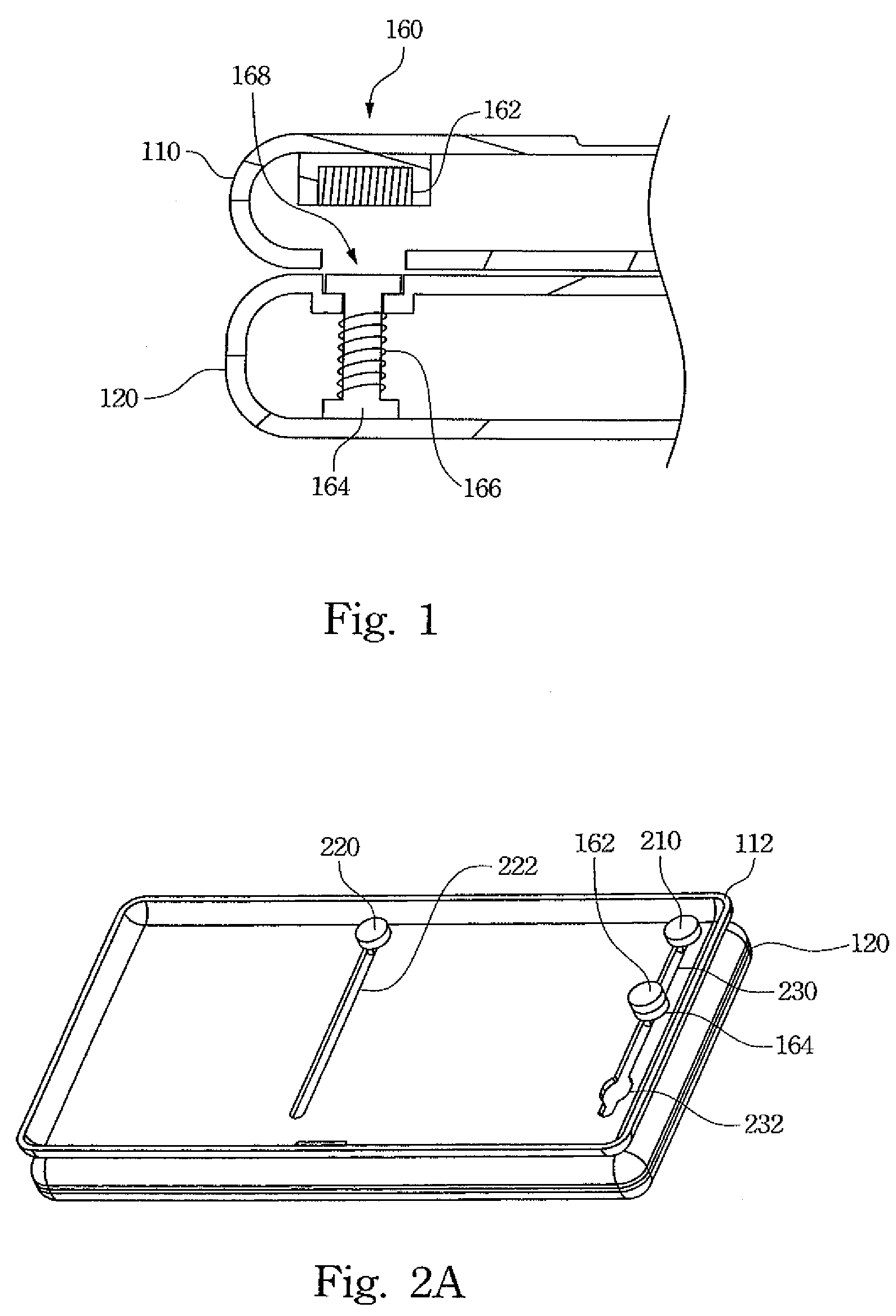
[0021]FIG. 1 illustrates a dynamic sliding module according to the present invention. An electronic device includes a first electronic module 110, a second electronic module 120, and a dynamic sliding module 160. The first electronic module 110 and the second electronic module 120 are slidable relative to each other so as to expose inner surfaces of the first electronic module 110 and the second electronic module 120.

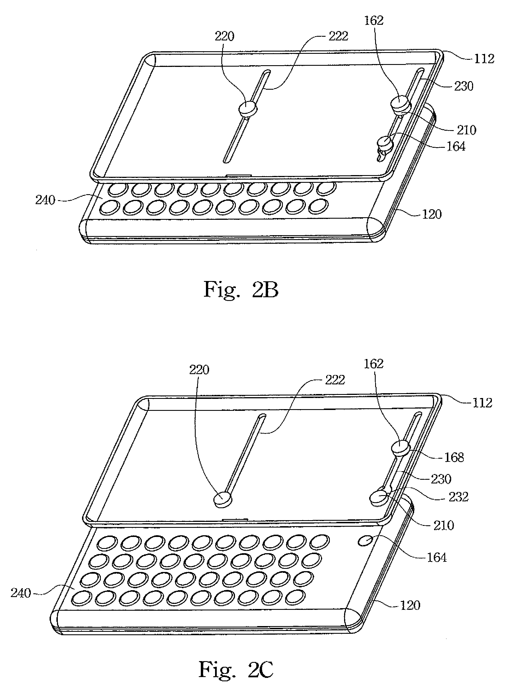
[0022]The dynamic sliding module 160 includes a guiding device, such as an attracting device 162 shown in FIG. 1, a dynamic slide 164, and sliding tracks (referring to FIGS. 2A to 2C). While the dynamic slide 164 disposed on the second electronic module 120 is aligned w...


PUM


Abstract

A dynamic sliding module is described. The dynamic sliding module includes a track, a dynamic slide, and a guiding device. The track includes a first opening and the guiding device is disposed adjacent to the first opening. When the dynamic slide slides along the track and aligns with the first opening, the guiding device provides a guiding force to guide the dynamic slide to move toward the first opening and enter into the track for sliding thereon. The track further includes a second opening to allow the dynamic slide to be withdrawn form the track. The dynamic sliding module further includes an elastic device and / or a wedge-shaped device disposed adjacent to the second opening to assist the dynamic slide to be withdrawn from the track.

Description

RELATED APPLICATIONS[0001]The present application is based on, and claims priority from, Taiwan Application Serial Number 94147789, filed Dec. 30, 2005, the disclosure of which is hereby incorporated by reference herein in its entirety.FIELD OF THE INVENTION[0002]The present invention generally relates to a dynamic sliding module for an electronic device. More particularly, this invention relates to a magnetically dynamic sliding module for an electronic device.BACKGROUND OF THE INVENTION[0003]Since wireless communication technology is highly developed, mobile phones are becoming increasingly light and easy to hold. Nowadays, most people use mobile phones to communicate with others. Therefore, the mobile phone has become a necessary electronic device in people's lives[0004]Due to the popularity of mobile phones, mobile phone manufacturers are working extremely hard to increase mobile phone functions in order to satisfy various requirements desired by users. For example, some of the ...

Claims


Application Information

Patent Timeline
Patent Type & Authority Patents(United States)
IPC IPC(8): H05K5/00
CPCH04M1/0237
Inventor SHIH, CHIN-CHUNGCHEN, CHING-SHIH
Owner HTC CORP
Learn More